crwdns2915892:0crwdne2915892:0
Use this guide to replace the upper case, including the backlit keyboard.
crwdns2942213:0crwdne2942213:0
-
crwdns2935267:0crwdne2935267:0P5 Pentalobe Screwdriver Retina MacBook Pro and Air$5.99
-
Use a P5 Pentalobe driver to remove ten screws securing the lower case, of the following lengths:
-
Two 9 mm screws
-
Eight 2.6 mm screws
-
-
-
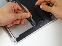
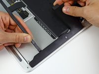
Wedge your fingers between the display and the lower case and pull upward to pop the lower case off the Air.
-
Remove the lower case and set it aside.
-
-
-
Grab the clear plastic pull tab attached to the battery connector and pull it toward the front edge of the Air to disconnect the battery from the logic board.
-
-
-
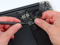
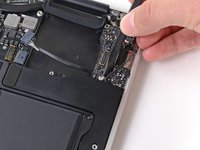
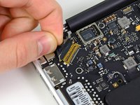
Use the flat end of a spudger to pry the I/O board cable connector upward out of its socket on the I/O board.
-
-
-
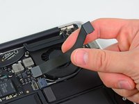
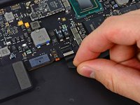
Carefully peel the I/O board cable from the top of the fan.
-
-
-
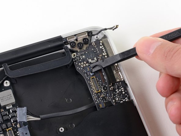
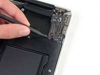
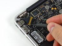
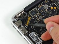
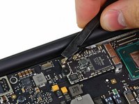
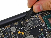
While gently pulling the I/O board cable upward near its connection to the logic board, use the tip of a spudger to pry upward on alternating sides of the connector to help "walk" it out of its socket.
-
Remove the I/O board cable.
-
-
-
Use the tip of a spudger to carefully flip up the retaining flap on the fan cable ZIF socket.
-
-
-
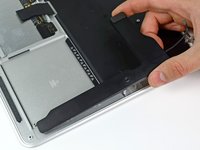
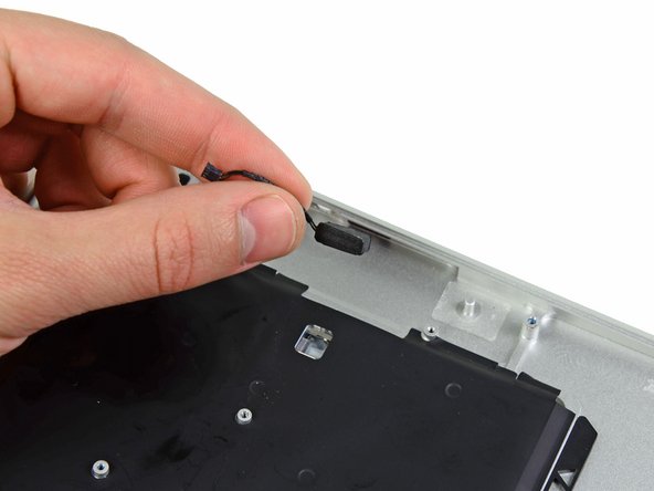
Peel the rubber gasket off the adhesive on the top of the fan.
-
-
-
Remove the following three screws securing the fan to the upper case:
-
One 3.6 mm T5 Torx screw
-
One 2.7 mm T5 Torx screw
-
One 3.6 mm T5 Torx screw with a short head
-
-
-
Lift the fan out of the upper case and carefully pull the fan ribbon cable out of its socket as you remove it from the Air.
-
-
-
Disconnect the I/O board by pulling the power cable away from its socket on the logic board.
-
-
-
Pull the camera cable parallel to the face of the I/O board toward the hinge of the Air to disconnect it from its socket, using the tip of a spudger to help push the connector out of its socket.
-
-
-
Use the flat end of a spudger to pry the left speaker cable connector up and out of its socket on the I/O board.
-
-
-
Use the tip of a spudger to flip up the retaining flap securing the microphone ribbon cable to the I/O board.
-
Use the tip of a spudger to remove the volume button ribbon cable from its ZIF connector on the I/O board.
-
-
-
-
Remove the single 4.0 mm T5 Torx screw securing the I/O board to the upper case.
-
-
-
Carefully lift the I/O board from its edge nearest the logic board and remove it from the upper case.
-
-
-
Remove the following five screws securing the battery to the upper case:
-
Three 6.3 mm T5 Torx screws
-
Two 2.4 mm T5 Torx screws
-
-
-
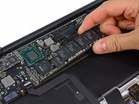
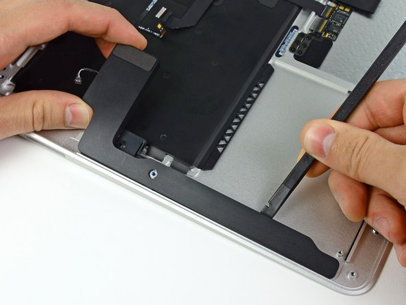
Lift the battery from its edge nearest the logic board and remove it from the upper case.
-
-
-
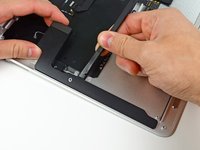
Use the tip of a spudger or your fingernail to flip up the retaining flap on the trackpad ribbon cable ZIF socket.
-
Be sure you are prying up on the hinged retaining flap, not the socket itself.
-
-
-
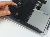
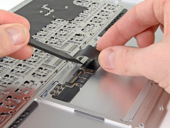
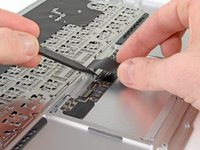
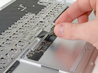
Use the tip of a spudger to flip up the retaining flap on the keyboard backlight ribbon cable ZIF socket.
-
Use your spudger to help pull the cable out of its socket.
-
-
-
Use the flat end of a spudger to pry the right speaker cable connector up and out of its socket on the logic board.
-
-
-
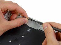
Gently push the tip of a spudger under the black plastic flap stuck to the display data cable lock to make the lock pop upward and away from the socket.
-
While holding the lock away from the socket, use the tip of a spudger and your fingers to gently remove the display data cable from its socket.
-
-
-
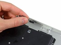
Use the flat end of a spudger to pry both antenna cable connectors up and off their sockets on the AirPort/Bluetooth card.
-
-
-
Gently de-route the antenna cables from the slot cut into the logic board.
-
-
-
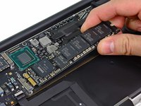
Remove the single 2.85 mm T5 Torx screw securing the SSD to the logic board.
-
-
-
Pull the drive straight out of its socket and remove it from the logic board.
-
-
-
Remove the six 6.3 mm T5 Torx screws securing the logic board to the upper case.
-
-
-
Remove the inner two 4.9 mm T8 Torx screws securing the antenna cable retainer and left clutch hinge to the upper case.
-
-
-
Push the antenna cable retainer away slightly and remove the 3 mm T5 Torx screw securing the end of the heat sink to the upper case.
-
-
-
Carefully remove the logic board assembly from the upper case, minding any cables that may get caught.
-
-
-
Gently de-route the antenna cables out of the channel cut into the upper case.
-
-
-
Remove the inner two 4.9 mm T8 Torx screws securing the right display hinge to the upper case.
-
-
-
Open the display until it is perpendicular to the upper case and place it on a table as shown.
-
While holding the MacBook Air steady, remove the remaining 4.9 mm T8 Torx screw from the lower display bracket.
-
-
-
Remove the last 4.9 mm T8 Torx screw securing the display to the upper case.
-
-
-
Push the upper case slightly toward the display assembly, then rotate it away from the front of the display assembly.
-
Once the two display hinges have cleared the upper case, remove the display and set it aside.
-
-
-
Use the flat end of a spudger to pry the right speaker off the adhesive securing it to the upper case.
-
Remove the right speaker from the upper case.
-
-
-
Use the flat end of a spudger to pry the left speaker off the adhesive securing it to the upper case.
-
Remove the left speaker from the upper case.
-
-
-
Use the tip of a spudger to pry the microphone away from the left side of the upper case.
-
Remove the microphone from the upper case.
-
Upper case remains.
-
-
-
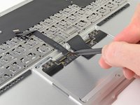
Use the tip of a spudger or your fingernail to flip up the retaining flap on the trackpad ribbon cable ZIF socket.
-
Pull the trackpad ribbon cable straight out of its socket toward the rear edge of the Air.
-
-
-
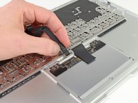
While carefully lifting the keyboard ribbon cable with one hand, use the tip of a spudger or your fingernail to flip up the retaining flap on the keyboard ribbon cable ZIF socket.
-
Pull the keyboard ribbon cable straight out of its socket toward the front edge of the Air.
-
-
-
Remove the following seven screws:
-
Six 1.6 mm Phillips screws securing the trackpad to the upper case.
-
One 1.4 mm T5 Torx set screw from its tapped hole near the front edge of the upper case.
-
-
-
Carefully lift the edge of the trackpad closest to the keyboard from its recess in the upper case by lifting it away from the brackets attached to the upper case.
-
Remove the trackpad from the upper case.
-
The upper case remains.
-


To reassemble your device, follow these instructions in reverse order.
To reassemble your device, follow these instructions in reverse order.
crwdns2935221:0crwdne2935221:0
crwdns2935229:062crwdne2935229:0

crwdns2947412:09crwdne2947412:0
On step 41 the 1.4 mm T5 Torx set screw remember that this screw does not come out. I was racking my brain for like 30 minutes and realized that this screw is not and can not be removed, rather it's just used to adjust the sensitivity of the clicking on the mouse pad.
I got mine out, but it was unnecessary for the procedure. You're right that it doesn't hold anything down really.
lionfish -
I had a Torx 6 in order to not strip the screw...
I spilt liquid on my MacBook Air and luckily only busted the keyboard, mainly the power and right arrow key buttons.
I purchased the uppercase from iFixit and it is a good quality part. The install took about 45 minutes, but there was a good hour of troubleshooting afterwards. See my comment on connecting the I/O connector cable above.
After doing any sort of hardware install, especially one as extensive as this, run the Apple Hardware Test application by holding down the D button while booting. It looks at a range of issues that you might miss (like a fan that doesn't spin!) that could cause you problems down the track.
Happy repairs.
This was an awesome and clearly understandable guide, helped by color-coded circles for the various screw sizes! I disassembled, replaced the top and keyboard and reassembled in less than an hour, with my son watching over my shoulder. Well done!