crwdns2915892:0crwdne2915892:0
Use this guide to replace a dead logic board.
crwdns2942213:0crwdne2942213:0
-
crwdns2935267:0crwdne2935267:0P5 Pentalobe Screwdriver Retina MacBook Pro and Air$5.99
-
Use a P5 Pentalobe driver to remove ten screws securing the lower case, of the following lengths:
-
Two 9 mm screws
-
Eight 2.6 mm screws
-
-
-
Wedge your fingers between the display and the lower case and pull upward to pop the lower case off the Air.
-
Remove the lower case and set it aside.
-
-
-
Grab the clear plastic pull tab attached to the battery connector and pull it toward the front edge of the Air to disconnect the battery from the logic board.
-
-
-
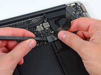
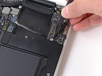
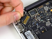
Use the flat end of a spudger to pry the I/O board cable connector upward out of its socket on the I/O board.
-
-
-
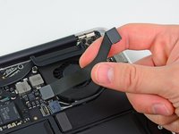
Carefully peel the I/O board cable from the top of the fan.
-
-
-
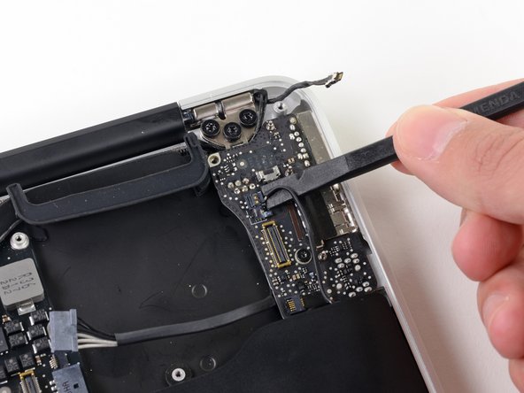
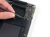
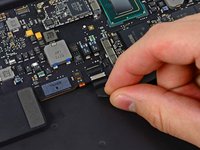
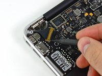
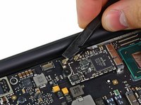
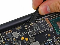
While gently pulling the I/O board cable upward near its connection to the logic board, use the tip of a spudger to pry upward on alternating sides of the connector to help "walk" it out of its socket.
-
Remove the I/O board cable.
-
-
-
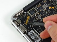
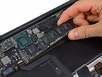
Use the tip of a spudger to carefully flip up the retaining flap on the fan cable ZIF socket.
-
-
-
Peel the rubber gasket off the adhesive on the top of the fan.
-
-
-
Remove the following three screws securing the fan to the upper case:
-
One 3.6 mm T5 Torx screw
-
One 2.7 mm T5 Torx screw
-
One 3.6 mm T5 Torx screw with a short head
-
-
-
Lift the fan out of the upper case and carefully pull the fan ribbon cable out of its socket as you remove it from the Air.
-
-
-
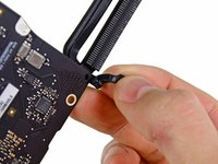
Disconnect the I/O board by pulling the power cable away from its socket on the logic board.
-
-
-
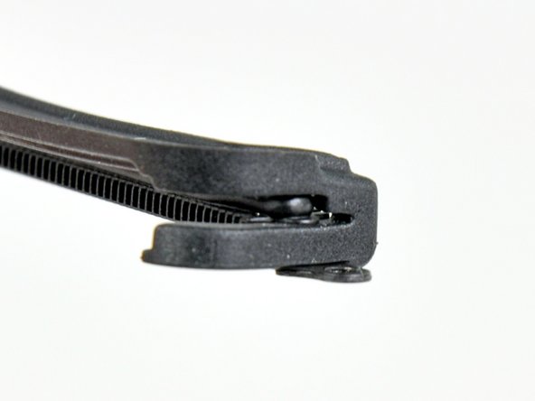
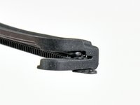
Pull the camera cable parallel to the face of the I/O board toward the hinge of the Air to disconnect it from its socket, using the tip of a spudger to help push the connector out of its socket.
-
-
-
-
Use the flat end of a spudger to pry the left speaker cable connector up and out of its socket on the I/O board.
-
-
-
Use the tip of a spudger to flip up the retaining flap securing the microphone ribbon cable to the I/O board.
-
Use the tip of a spudger to remove the volume button ribbon cable from its ZIF connector on the I/O board.
-
-
-
Remove the single 4.0 mm T5 Torx screw securing the I/O board to the upper case.
-
-
-
Carefully lift the I/O board from its edge nearest the logic board and remove it from the upper case.
-
-
-
Remove the following five screws securing the battery to the upper case:
-
Three 6.3 mm T5 Torx screws
-
Two 2.4 mm T5 Torx screws
-
-
-
Lift the battery from its edge nearest the logic board and remove it from the upper case.
-
-
-
Use the tip of a spudger or your fingernail to flip up the retaining flap on the trackpad ribbon cable ZIF socket.
-
Be sure you are prying up on the hinged retaining flap, not the socket itself.
-
-
-
Use the tip of a spudger to flip up the retaining flap on the keyboard backlight ribbon cable ZIF socket.
-
Use your spudger to help pull the cable out of its socket.
-
-
-
Use the flat end of a spudger to pry the right speaker cable connector up and out of its socket on the logic board.
-
-
-
Gently push the tip of a spudger under the black plastic flap stuck to the display data cable lock to make the lock pop upward and away from the socket.
-
While holding the lock away from the socket, use the tip of a spudger and your fingers to gently remove the display data cable from its socket.
-
-
-
Use the flat end of a spudger to pry both antenna cable connectors up and off their sockets on the AirPort/Bluetooth card.
-
-
-
Gently de-route the antenna cables from the slot cut into the logic board.
-
-
-
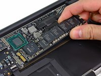
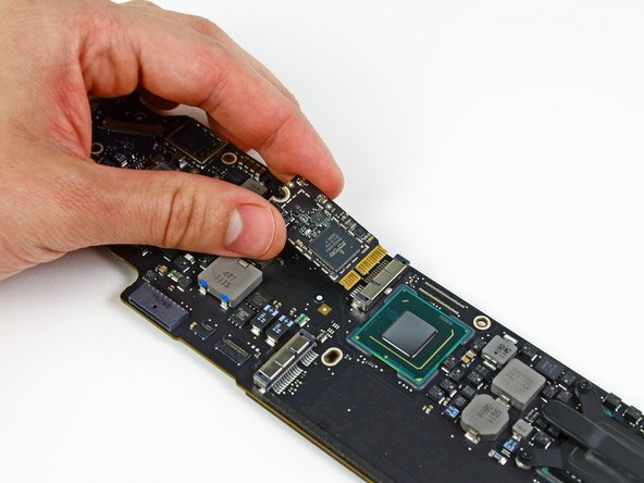
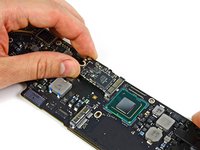
Remove the single 2.85 mm T5 Torx screw securing the SSD to the logic board.
-
-
-
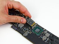
Pull the drive straight out of its socket and remove it from the logic board.
-
-
-
Remove the six 6.3 mm T5 Torx screws securing the logic board to the upper case.
-
-
-
Remove the inner two 4.9 mm T8 Torx screws securing the antenna cable retainer and left clutch hinge to the upper case.
-
-
-
Push the antenna cable retainer away slightly and remove the 3 mm T5 Torx screw securing the end of the heat sink to the upper case.
-
-
-
Carefully remove the logic board assembly from the upper case, minding any cables that may get caught.
-
-
-
Remove the single 2.9 mm T5 Torx screw securing the AirPort/Bluetooth card to the logic board.
-
-
-
Slightly lift the free end of the AirPort/Bluetooth board and pull it out of its socket on the logic board.
-
Remove the AirPort/Bluetooth board from the logic board.
-
-
-
Remove the four 2.5 mm T5 Torx screws securing the heat sink to the logic board.
-
-
-
Remove the heat sink from the logic board.
-


To reassemble your device, follow these instructions in reverse order.
crwdns2935221:0crwdne2935221:0
crwdns2935229:055crwdne2935229:0

crwdns2947412:09crwdne2947412:0
Those connections are scary small! The speaker connections in particular are very fragile and hard to get under to lift off. One of mine came apart, but it could be reassembled by first placing the plastic connector in the socket and carefully connecting the metal terminations into it. Be careful to orient the slot in the wire termination so it is vertical to interface with the lug in the socket, if that happens to you.
I had the dreaded "3 beep" (memory failure) problem and ordered a new logic board. Only when I had the old board out did I realize there was a compatibility problem- different board versions, connectors did not match. Since I was stuck anyway, I baked my old board in the oven (325 for 10 minutes) and reassembled it all so I would not lose any parts. I was surprised to have it boot up with the old (baked) board!
I hate these lazy Haynes Manual type of articles that just tear down a product and give zero insight to the actual assembly. It's the type of knowledge that is just enough to be dangerous. Countless of times I've encountered that assembly IS NOT reverse of disassembly, where a specific tool or technique is required that is not covered in this lazy style of articles.
9 times out of 10, disassembly is the easy part and assembly the hard part.
I did not find that to be an issue with this guide, reassembly was quite easy and was just the reverse of assembly. The whole thing took by less than 90 minutes beginning to end.
I feel that almost all assembly steps don't need repeating( a follow up reassemble step). In my opinion, assemble/reassemble steps involving a ribbon/flex cable and ZIF socket would be helpful, especially for newbies. Thats just one techs opinion. All that said, I feel the author did a fantastic job and I had no trouble removing/reinstalling my logic board and components. Thank you A. Goldberg and keep up the good work.
Great guide! I wish I had found this before I followed the ‘tear down’ guide; hopefully I didn’t break anything doing it that way. The I/O board camera connector was the worst — it really requires quite a pull to release. It would be ideal to have a close-up showing exactly where to put the spudger tip to push. Also, the speakers were rather well glued down, but eventually did release. Pointing out where the glue point is (in the notch just before the bend on the right=hand one) would have helped me.