crwdns2915892:0crwdne2915892:0
Prerequisite to removing the upper case.
crwdns2942213:0crwdne2942213:0
-
crwdns2935267:0crwdne2935267:0P5 Pentalobe Screwdriver Retina MacBook Pro and Air$5.99
-
Use a P5 Pentalobe driver to remove ten screws securing the lower case, of the following lengths:
-
Two 9 mm screws
-
Eight 2.6 mm screws
-
-
-
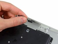
Wedge your fingers between the display and the lower case and pull upward to pop the lower case off the Air.
-
Remove the lower case and set it aside.
-
-
-
Grab the clear plastic pull tab attached to the battery connector and pull it toward the front edge of the Air to disconnect the battery from the logic board.
-
-
-
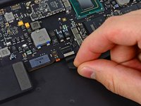
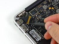
Use the flat end of a spudger to pry the I/O board cable connector upward out of its socket on the I/O board.
-
-
-
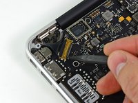
Carefully peel the I/O board cable from the top of the fan.
-
-
-
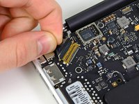
While gently pulling the I/O board cable upward near its connection to the logic board, use the tip of a spudger to pry upward on alternating sides of the connector to help "walk" it out of its socket.
-
Remove the I/O board cable.
-
-
-
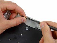
Use the tip of a spudger to carefully flip up the retaining flap on the fan cable ZIF socket.
-
-
-
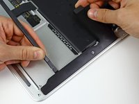
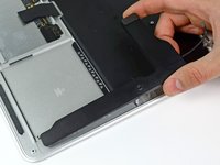
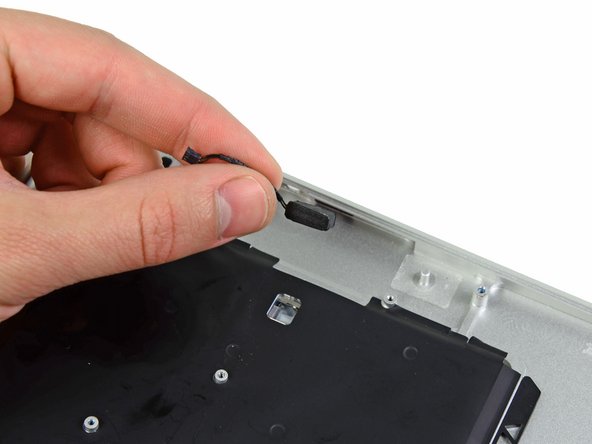
Peel the rubber gasket off the adhesive on the top of the fan.
-
-
-
Remove the following three screws securing the fan to the upper case:
-
One 3.6 mm T5 Torx screw
-
One 2.7 mm T5 Torx screw
-
One 3.6 mm T5 Torx screw with a short head
-
-
-
Lift the fan out of the upper case and carefully pull the fan ribbon cable out of its socket as you remove it from the Air.
-
-
-
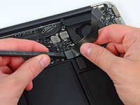
Disconnect the I/O board by pulling the power cable away from its socket on the logic board.
-
-
-
Pull the camera cable parallel to the face of the I/O board toward the corner of the Air to disconnect it from its socket, using the tip of a spudger to help push the connector out of its socket.
-
-
-
-
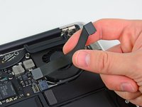
Use the flat end of a spudger to pry the left speaker cable connector up and out of its socket on the I/O board.
-
De-route the left speaker cable from its retainer on the I/O board.
-
-
-
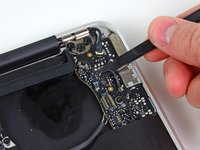
Use the flat end of a spudger to pry the microphone cable connector up and out of its socket on the I/O board.
-
-
-
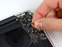
Remove the single 3.6 mm T5 Torx screw securing the I/O board to the upper case.
-
-
-
Carefully lift the I/O board from its edge nearest the logic board and remove it from the upper case.
-
-
-
Use the tip of a spudger or your fingernail to flip up the retaining flap on the trackpad ribbon cable ZIF socket.
-
Be sure you are prying up on the hinged retaining flap, not the socket itself.
-
-
-
Use the tip of a spudger to flip up the retaining flap on the keyboard backlight ribbon cable ZIF socket.
-
Use your spudger to help pull the cable out of its socket.
-
-
-
Use the flat end of a spudger to pry the right speaker cable connector up and out of its socket on the logic board.
-
-
-
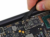
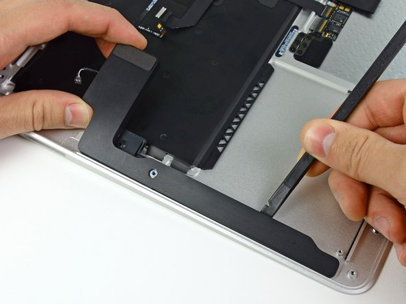
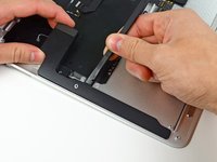
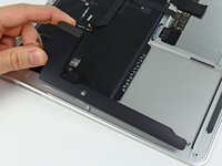
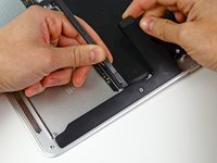
Gently push the tip of a spudger under the black plastic flap stuck to the display data cable lock to make the lock pop upward and away from the socket.
-
While holding the lock away from the socket, use the tip of a spudger and your fingers to gently remove the display data cable from its socket.
-
-
-
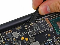
Use the flat end of a spudger to pry both antenna cable connectors up and off their sockets on the AirPort/Bluetooth card.
-
-
-
Gently de-route the antenna cables from the slot cut into the logic board.
-
-
-
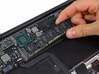
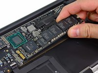
Remove the single 2.85 mm T5 Torx screw securing the SSD to the logic board.
-
-
-
Pull the drive straight out of its socket and remove it from the logic board.
-
-
-
Remove the six 6.3 mm T5 Torx screws securing the logic board to the upper case.
-
-
-
Remove the inner two 4.9 mm T8 Torx screws securing the antenna cable retainer and left clutch hinge to the upper case.
-
-
-
Push the antenna cable retainer away slightly and remove the 3 mm T5 Torx screw securing the end of the heat sink to the upper case.
-
-
-
Carefully remove the logic board assembly from the upper case, minding any cables that may get caught.
-
-
-
Gently de-route the antenna cables out of the channel cut into the upper case.
-
-
-
Remove the inner two 4.9 mm T8 Torx screws securing the right display hinge to the upper case.
-
-
-
Open the display until it is perpendicular to the upper case and place it on a table as shown.
-
While holding the MacBook Air steady, remove the remaining 4.9 mm T8 Torx screw from the lower display bracket.
-
-
-
Remove the last 4.9 mm T8 Torx screw securing the display to the upper case.
-
-
-
Push the upper case slightly toward the display assembly, then rotate it away from the front of the display assembly.
-
Once the two display hinges have cleared the upper case, remove the display and set it aside.
-
-
-
Use the flat end of a spudger to pry the right speaker off the adhesive securing it to the upper case.
-
Remove the right speaker from the upper case.
-
-
-
Use the flat end of a spudger to pry the left speaker off the adhesive securing it to the upper case.
-
Remove the left speaker from the upper case.
-
-
-
Use the tip of a spudger to pry the microphone away from the left side of the upper case.
-
Remove the microphone from the upper case.
-
Upper case remains.
-


crwdns2935221:0crwdne2935221:0
crwdns2935229:07crwdne2935229:0
