crwdns2915892:0crwdne2915892:0
Use this guide to replace the upper case.
crwdns2942213:0crwdne2942213:0
-
crwdns2935267:0crwdne2935267:0P5 Pentalobe Screwdriver Retina MacBook Pro and Air$5.99
-
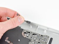
Remove the following ten screws:
-
Two 9 mm 5-point Pentalobe screws
-
Eight 2.6 mm 5-point Pentalobe screws
-
-
-
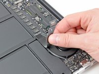
Wedge your fingers between the display and the lower case and pull upward to pop the lower case off the Air.
-
Remove the lower case and set it aside.
-
-
-
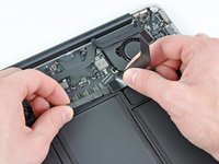
Grab the clear plastic pull tab attached to the battery connector and pull it toward the front edge of the Air to disconnect the battery from the logic board.
-
-
-
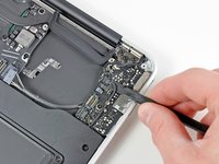
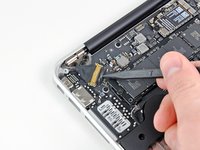
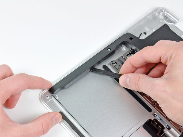
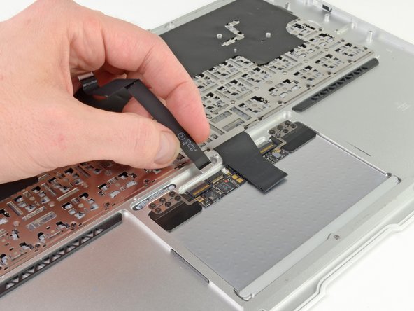
Use the flat end of a spudger to pry the I/O board cable connector upward out of its socket on the I/O board.
-
-
-
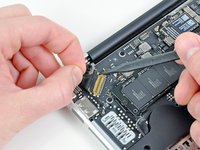
Carefully peel the I/O board cable from the top of the fan.
-
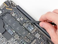
While gently pulling the I/O board cable upward near its connection to the logic board, use the tip of a spudger to pry upward on alternating sides of the connector to help "walk" it out of its socket.
-
Remove the I/O board cable.
-
-
-
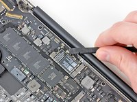
Use the tip of a spudger to carefully flip up the retaining flap on the fan cable ZIF socket.
-
-
-
Peel the rubber gasket off the adhesive on the top of the fan.
-
-
-
Remove the following three screws securing the fan to the upper case:
-
One 3.6 mm T5 Torx screw
-
One 2.7 mm T5 Torx screw
-
One 3.6 mm T5 Torx screw with a short head
-
-
-
Lift the fan out of the upper case and carefully pull the fan ribbon cable out of its socket as you remove it from the Air.
-
-
-
Disconnect the I/O board by pulling the power cable away from its socket on the logic board.
-
-
-
Pull the camera cable parallel to the face of the I/O board toward the corner of the Air to disconnect it from its socket, using the tip of a spudger to help push the connector out of its socket.
-
-
-
Use the flat end of a spudger to pry the left speaker cable connector up and out of its socket on the I/O board.
-
De-route the left speaker cable from its retainer on the I/O board.
-
-
-
Use the flat end of a spudger to pry the microphone cable connector up and out of its socket on the I/O board.
-
-
-
Remove the single 3.6 mm T5 Torx screw securing the I/O board to the upper case.
-
-
-
Carefully lift the I/O board from its edge nearest the logic board and remove it from the upper case.
-
-
-
-
Remove the following five screws securing the battery to the upper case:
-
Three 6.3 mm T5 Torx screws
-
Two 2.4 mm T5 Torx screws
-
-
-
Lift the battery from its edge nearest the logic board and remove it from the upper case.
-
-
-
Use the tip of a spudger or your fingernail to flip up the retaining flap on the trackpad ribbon cable ZIF socket.
-
Pull the trackpad ribbon cable straight out of its socket toward the front edge of the Air.
-
-
-
Use the flat end of a spudger to pry the right speaker cable connector up and out of its socket on the logic board.
-
-
-
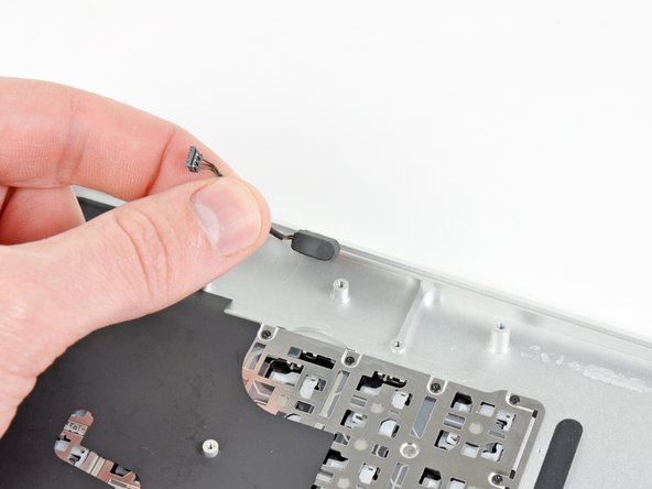
Gently push the tip of a spudger under the black plastic flap stuck to the display data cable lock to make the lock pop upward and away from the socket.
-
While holding the lock away from the socket, use the tip of a spudger and your fingers to gently remove the display data cable from its socket by sliding it toward the corner of the Air.
-
-
-
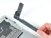
Use the flat end of a spudger to pry both antenna cable connectors up and off their sockets on the AirPort/Bluetooth card.
-
-
-
Gently de-route the antenna cables from the slot cut into the logic board.
-
-
-
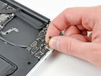
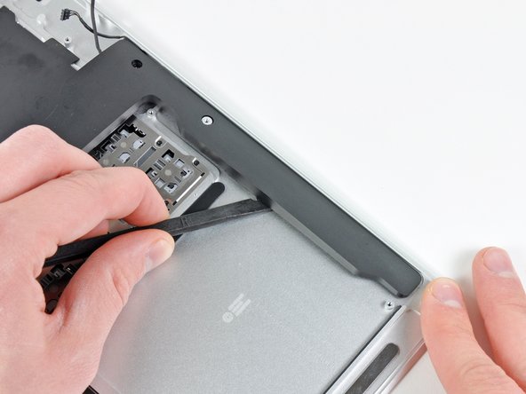
Remove the single 2.85 mm T5 Torx screw securing the SSD to the logic board.
-
-
-
Pull the drive straight out of its socket and remove it from the logic board.
-
-
-
Remove the six 6.3 mm T5 Torx screws securing the logic board to the upper case.
-
-
-
Remove the inner two 4.9 mm T8 Torx screws securing the antenna cable retainer and left clutch hinge to the upper case.
-
-
-
Push the antenna cable retainer away slightly and remove the 3 mm T5 Torx screw securing the end of the heat sink to the upper case.
-
-
-
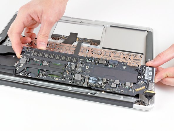
Carefully remove the logic board assembly from the upper case, minding any cables that may get caught.
-
-
-
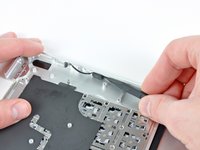
Gently de-route the antenna cables out of the channel cut into the upper case.
-
-
-
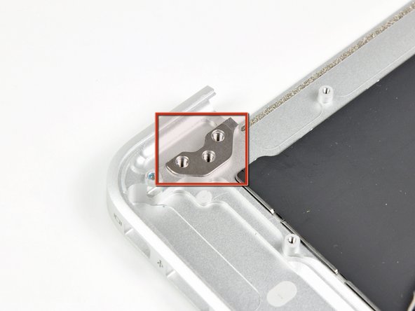
Remove the inner two 4.9 mm T8 Torx screws securing the right display hinge to the upper case.
-
-
-
Open the display until it is perpendicular to the upper case and place it on a table as shown.
-
While holding the Air steady, remove the remaining 4.9 mm T8 Torx screw from the lower display bracket.
-
-
-
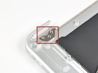
Remove the last 4.9 mm T8 Torx screw securing the display to the upper case.
-
-
-
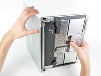
Push the upper case slightly toward the display assembly, then rotate it away from the front of the display assembly.
-
Once the two display hinges have cleared the upper case, remove the display and set it aside.
-
-
-
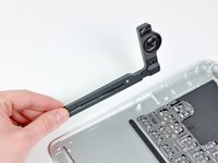
Remove the single 2.7 mm T5 Torx screw securing the right speaker to the upper case.
-
-
-
Use the flat end of a spudger to pry the right speaker off the adhesive securing it to the upper case.
-
Remove the right speaker from the upper case.
-
-
-
Remove the single 2.7 mm T5 Torx screw securing the left speaker to the upper case.
-
-
-
Use the flat end of a spudger to pry the left speaker off the adhesive securing it to the upper case.
-
Remove the left speaker from the upper case.
-
-
-
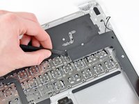
Use the tip of a spudger to pry the microphone away from the left side of the upper case.
-
Remove the microphone from the upper case.
-
Upper case remains.
-
-
-
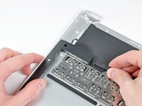
Use the tip of a spudger or your fingernail to flip up the retaining flap on the trackpad ribbon cable ZIF socket.
-
Pull the trackpad ribbon cable straight out of its socket toward the rear edge of the Air.
-
-
-
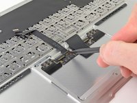
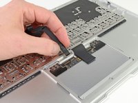
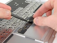
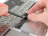
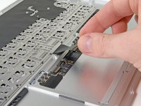
While carefully lifting the keyboard ribbon cable with one hand, use the tip of a spudger or your fingernail to flip up the retaining flap on the keyboard ribbon cable ZIF socket.
-
Pull the keyboard ribbon cable straight out of its socket toward the front edge of the Air.
-
-
-
Remove the following seven screws:
-
Six 1.6 mm Phillips screws securing the the trackpad to the upper case.
-
One 1.4 mm T5 Torx set screw near the front edge of the upper case.
-
-
-
Carefully lift the edge of the trackpad closest to the keyboard from its recess in the upper case by lifting it away from the brackets attached to the upper case.
-
Remove the trackpad from the upper case.
-


To reassemble your device, follow these instructions in reverse order.
To reassemble your device, follow these instructions in reverse order.
crwdns2935221:0crwdne2935221:0
crwdns2935229:036crwdne2935229:0

crwdns2947412:07crwdne2947412:0
I'm pretty experienced in dismantling/reassembling Aluminum MacBook Pros, plastic MacBooks, aluminum Powerbooks and various iBooks and this was not bad at all. Mostly just time-consuming.
I'm not sure I'd rate it as "difficult" for those with previous experience. The screw count is particularly low by comparison to other machines I've worked on, and there are only a few different types of screw.
The new top case arrived with the adhesives to re-secure the speakers, new screws to attach the trackpad, and the microphone was pre-installed.
Excellent guide, and a great help as always. Thanks!
I just repaired my mba after spilling some juice on it... I did it in about 2hours, i kept track of the screws in each step and i must say it wasn't difficult at all, and i have no experience with computer so.. Just be careful with some wires and when you disconnect the monitor but that's all. I'm so happy my mba works again! The upper case and the tools arrived very quick and with adhesives and some extra screws (much appreciated since the stock screws were kind of damaged and i had to break one) for the trackpad. Thanks ifixit!
Right On! I did the whole thing in 2 hours. Great guide and I would rate this task as medium not difficult. Thanks again spot on!!
Son of Raven
Just completed the upper case replacement today due to a failed keyboard and also a failed touch pad (due to liquid damage). Took a few hours to take it apart (and be careful as I was doing it) found hardest part was keeping track of screws and parts. I ended up using plastic red/white Solo cups with the Step # written on each cup (so you don't confuse the screws per step). Undoing the retaining clips for ribbon wires was hardest part highly recommend using a spudger with a fine tip as these are very tiny parts.
The instructions were great. I used a white plastic ice-tray to hold the screws and fill each cube up sequentially. All you have to do, is work backwards through the recesses to where you started. No way to mix things up and hard to tip over.