crwdns2915892:0crwdne2915892:0
Use this guide to replace the display assembly.
crwdns2942213:0crwdne2942213:0
-
crwdns2935267:0crwdne2935267:0P5 Pentalobe Screwdriver Retina MacBook Pro and Air$5.99
-
Remove the following ten screws:
-
Two 8 mm 5-point Pentalobe screws
-
Eight 2.5 mm 5-point Pentalobe screws
-
-
-
Wedge your fingers between the display and the lower case and pull upward to pop the lower case off the Air.
-
-
-
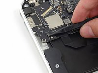
Use the flat end of a spudger to pry both short sides of the battery connector upward to disconnect it from its socket on the logic board.
-
Bend the battery cable slightly away from the logic board so the connector will not accidentally bend back and make contact with its socket.
-
-
-
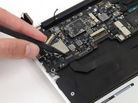
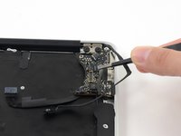
Use the flat end of a spudger to pry the left and right I/O board cable connectors up off their respective sockets on the I/O board.
-
-
-
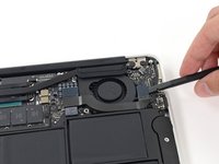
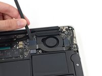
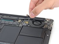
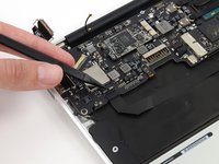
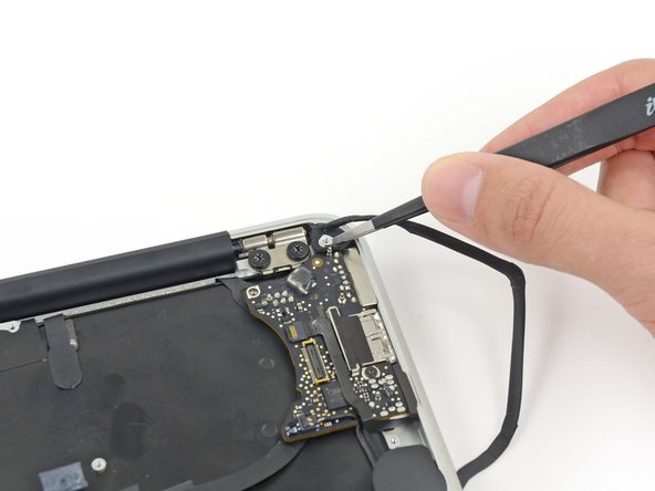
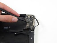
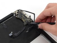
Use the tip of a spudger to carefully push on each side of the iSight camera cable connector to loosen it out of its socket on the logic board.
-
-
-
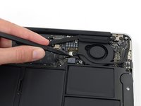
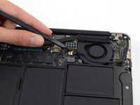
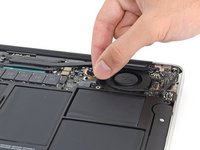
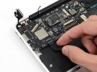
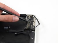
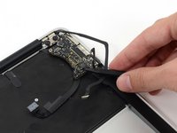
Peel the iSight camera cable up off the adhesive securing it to the fan.
-
-
-
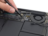
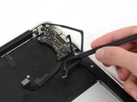
Use the tip of a spudger to carefully flip up the retaining flap on the fan cable ZIF socket.
-
-
-
Remove the following three screws securing the fan to the upper case:
-
Two 5.5 mm T5 Torx screws
-
One 4.6 mm T5 Torx screw
-
-
-
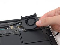
Lift, but do not remove the fan out of its recess in the upper case.
-
Carefully pull the fan ribbon cable out of its socket as you remove the fan from the Air.
-
-
-
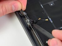
Use the flat end of a spudger to pry both antenna connectors up from their sockets on the AirPort/Bluetooth card, and move them out of the way.
-
-
-
Remove the following five screws securing the battery to the upper case:
-
Two 5.2 mm T5 Torx screws
-
One 6 mm T5 Torx screw
-
Two 2.6 mm T5 Torx screws
-
-
-
-
Lift the battery from its edge nearest the logic board and remove it from the upper case.
-
-
-
Disconnect the I/O board by pulling the power cable away from its socket on the logic board.
-
-
-
Use the tip of a spudger to de-route the antenna cables from their notches in the logic board.
-
-
-
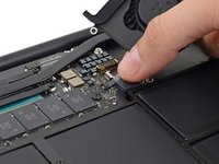
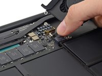
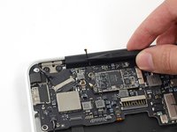
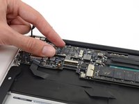
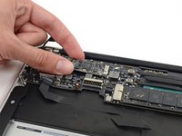
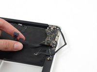
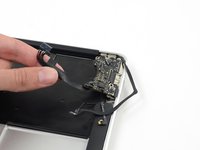
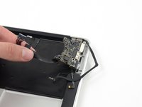
Gently push the tip of a spudger under the black plastic flap stuck to the display data cable lock to make the lock pop upward and away from the socket.
-
While holding the lock away from the socket, gently pull the display data cable out of its socket.
-
-
-
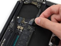
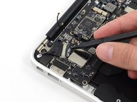
Use the tip of a spudger to pry under the speaker cable connector, lifting it straight up from its socket.
-
De-route the cable from its notch in the logic board.
-
-
-
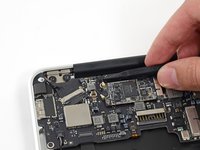
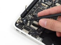
Use the tip of a spudger or your fingernail to flip up the retaining flap on the trackpad ribbon cable ZIF socket.
-
Pull the trackpad ribbon cable straight out of its socket toward the front edge of the Air.
-
-
-
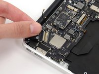
Use the tip of a spudger to flip up the retaining flap on the keyboard backlight ribbon cable ZIF socket.
-
Pull the keyboard backlight ribbon cable out of its socket.
-
-
-
Remove the single 2.9 mm T5 Torx screw securing the AirPort/Bluetooth card to the logic board.
-
-
-
Slightly lift the free end of the AirPort/Bluetooth board and pull it out of its socket on the logic board.
-
-
-
Remove the three 3.6 mm T5 Torx screws securing the logic board to the upper case.
-
In some models these are 3.1 mm T5 Torx screws.
-
-
-
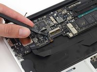
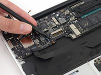
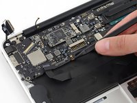
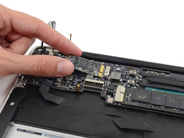
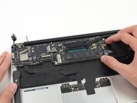
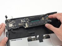
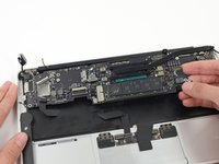
Gently lift the logic board assembly from the heat sink end and pull it away from the port side of the case to remove it from the Air.
-
-
-
Remove the small rubber gasket from the corner of the upper case nearest the the I/O board.
-
Remove the gasket from the corner nearest display cable connector.
-
-
crwdns2935267:0crwdne2935267:0Tweezers$4.99
-
-
Use the tip of a spudger to carefully flip up the retaining flap on the microphone cable ZIF socket.
-
With a pair of tweezers, pull the microphone ribbon cable straight out of its socket.
-
-
-
Use the tip of a spudger to pry under the speaker cable near the connector, lifting it straight up from its socket.
-
De-route the cable from its notch in the logic board.
-
-
-
Remove the single 3.6 mm T5 Torx screw securing the I/O board to the upper case.
-
-
-
Carefully lift the I/O board by its power cable and pull it away from the edge of the case.
-
-
-
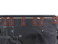
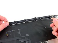
Peel up the six cable loops securing the antenna cables to the upper case.
-
Gently pull the cable loops slightly out of the channel cut into the upper case one at a time.
-
Use your spudger to open up the plastic loops as you de-route the antenna cables through them.
-
-
-
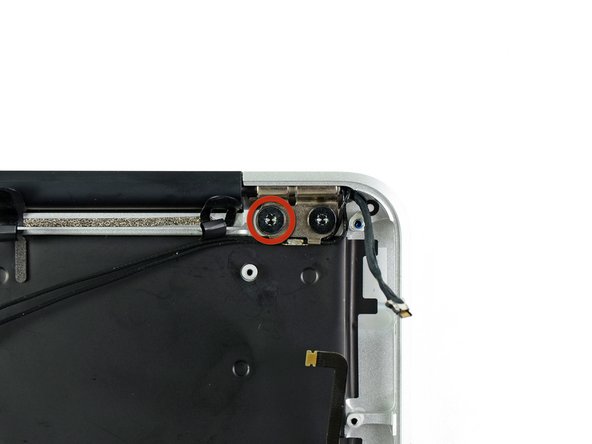
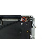
Remove the inner 4.9 mm T8 Torx screw securing each display hinge to the upper case (two screws total).
-
-
-
While holding the Air steady, remove the remaining 4.9 mm T8 Torx screw from the lower display bracket.
-
-
-
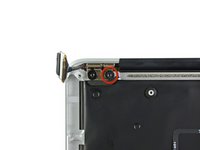
Remove the last 4.9 mm T8 Torx screw securing the display to the upper case.
-
-
-
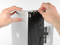
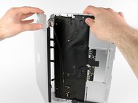
Push the upper case slightly toward the display assembly, then rotate it away from the front of the display assembly.
-
Once the two display hinges have cleared the upper case, remove the display.
-


To reassemble your device, follow these instructions in reverse order.
crwdns2935221:0crwdne2935221:0
crwdns2935229:030crwdne2935229:0


crwdns2947412:03crwdne2947412:0
Great tutorial. Easy to follow. Don't be afraid to do it.
I wish the tutorial showed the procedure for tearing down the LCD and backlight panel... So not fun.
is this Display of macbook air mid 2013 can fit into macbook air mid 2012?