crwdns2915892:0crwdne2915892:0
Use this guide to replace your MacBook Air's upper case. The upper case includes the keyboard and trackpad.
crwdns2942213:0crwdne2942213:0
-
crwdns2935267:0crwdne2935267:0P5 Pentalobe Screwdriver Retina MacBook Pro and Air$5.99
-
Remove the following ten screws:
-
Two 8 mm 5-point Pentalobe screws
-
Eight 2.5 mm 5-point Pentalobe screws
-
-
-
Wedge your fingers between the display and the lower case and pull upward to pop the lower case off the Air.
-
-
-
Use the flat end of a spudger to pry both short sides of the battery connector upward to disconnect it from its socket on the logic board.
-
Bend the battery cable slightly away from the logic board so the connector will not accidentally contact its socket.
-
-
-
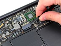
Remove the single 2.9 mm T5 Torx screw securing the SSD to the logic board.
-
-
-
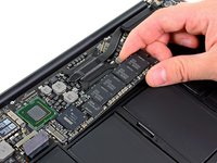
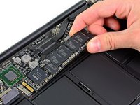
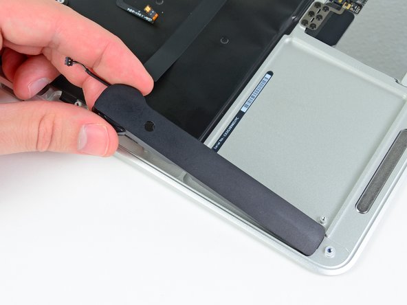
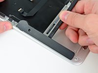
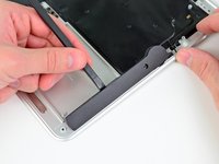
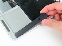
Use a spudger to help lift the free end of the SSD just enough to grab it with your other hand.
-
Pull the drive straight out of its socket and remove it from the logic board.
-
-
-
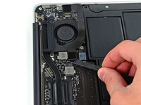
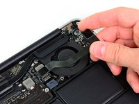
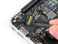
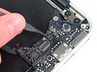
Use the flat end of a spudger to pry the I/O board cable up from its socket on the I/O board.
-
-
-
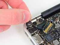
Peel the I/O board cable up from the adhesive securing it to the fan.
-
-
-
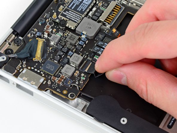
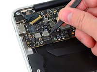
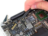
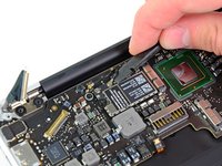
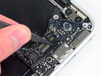
Use the flat end of a spudger to lift the I/O board connector up and out of its socket on the logic board
-
Remove the I/O board cable.
-
-
-
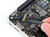
Use the tip of a spudger to carefully flip up the retaining flap on the fan cable ZIF socket.
-
-
-
Remove the following three screws securing the fan to the upper case:
-
Two 5.2 mm T5 Torx screws
-
One 3.6 mm T5 Torx screw
-
-
-
Lift the fan out of the upper case and carefully pull the fan ribbon cable out of its socket as you remove it from the Air.
-
-
-
Remove the following five screws securing the battery to the upper case:
-
Two 5.2 mm T5 Torx screws
-
One 6 mm T5 Torx screw
-
Two 2.6 mm T5 Torx screws
-
-
-
Lift the battery from its edge nearest the logic board and remove it from the upper case.
-
-
-
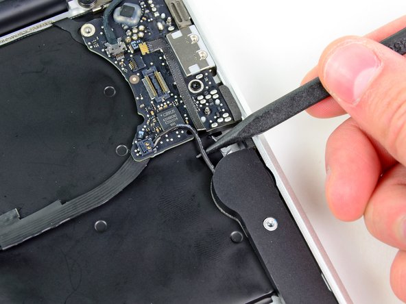
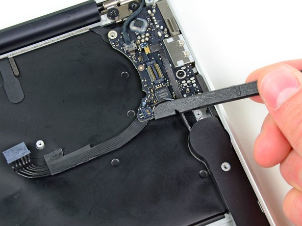
Use the flat end of a spudger to free the adhesive loop securing the I/O board power cable to the upper case.
-
Disconnect the I/O board by pulling the power cable away from its socket on the logic board.
-
-
-
Use the tip of a spudger to flip up the retaining flap on the keyboard backlight ribbon cable ZIF socket.
-
Pull the keyboard backlight ribbon cable out of its socket.
-
-
-
-
Use the tip of a spudger or your fingernail to flip up the retaining flap on the trackpad ribbon cable ZIF socket.
-
Pull the trackpad ribbon cable straight out of its socket toward the front edge of the Air.
-
-
-
Use the tip of a spudger to de-route the right speaker cable from the slot cut into the logic board.
-
-
-
Use the flat end of a spudger to pry the right speaker cable connector up and out of its socket on the logic board.
-
-
-
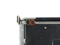
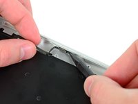
Gently push the tip of a spudger under the black plastic flap stuck to the display data cable lock to make the lock pop upward and away from the socket.
-
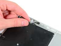
Remove the small rubber gasket from the corner of the upper case near the display data cable.
-
-
-
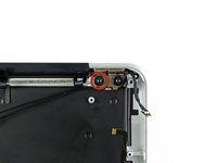
While holding the lock away from the socket, gently pull the display data cable out of its socket.
-
-
-
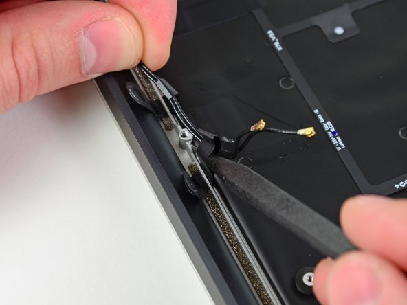
Use the flat end of a spudger to pry both antenna cable connectors up and off their sockets on the AirPort/Bluetooth card.
-
-
-
Gently de-route the antenna cables from the slot cut into the logic board.
-
-
-
Remove the three 3.6 mm T5 Torx screws securing the logic board to the upper case.
-
-
-
Gently lift the logic board assembly out of the upper case, minding the fragile heat sink and any cables that may get caught.
-
-
-
Remove the small rubber gasket from the corner of the upper case nearest the I/O board.
-
-
-
Use the tip of a spudger to carefully flip up the retaining flap on the microphone cable ZIF socket.
-
Pull the microphone ribbon cable straight out of its socket.
-
-
-
De-route the left speaker cable from the notch cut into the I/O board.
-
Use the flat end of a spudger to pry the left speaker cable connector up and out of its socket on the I/O board.
-
-
-
Pull the camera cable parallel to the face of the I/O board toward the rear edge of the Air to disconnect it from its socket.
-
-
-
Remove the single 3.6 mm T5 Torx screw securing the I/O board to the upper case.
-
-
-
Carefully lift the I/O board from its edge nearest the logic board and remove it from the upper case.
-
-
-
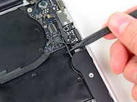
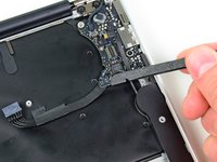
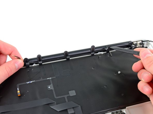
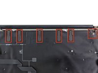
Peel up the six cable loops securing the antenna cables to the upper case.
-
Gently pull the cable loops slightly out of the channel cut into the upper case one at a time.
-
Use your spudger to open up the plastic loops as you de-route the antenna cables through them.
-
Repeat this for all of the retaining loops.
-
-
-
Remove the inner 4.9 mm T8 Torx screw securing each display hinge to the upper case (two screws total).
-
-
-
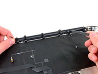
Open the display until it is perpendicular to the upper case and place it on a table as shown.
-
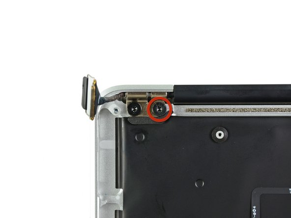
While holding the Air steady, remove the remaining 4.9 mm T8 Torx screw from the lower display bracket.
-
-
-
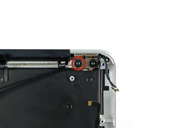
Remove the last 4.9 mm T8 Torx screw securing the display to the upper case.
-
-
-
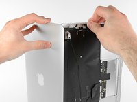
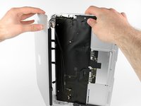
Push the upper case slightly toward the display assembly, then rotate it away from the front of the display assembly.
-
Once the two display hinges have cleared the upper case, remove the display and set it aside.
-
-
-
Use the flat end of a spudger to pry the right speaker off the adhesive securing it to the upper case.
-
Remove the right speaker from the upper case.
-
-
-
Use the flat end of a spudger to pry the left speaker off the adhesive securing it to the upper case.
-
Remove the left speaker from the upper case.
-
-
-
Use the tip of a spudger to pry the microphone away from the side of the upper case.
-
Remove the microphone from the upper case.
-
Upper case remains.
-
-
-
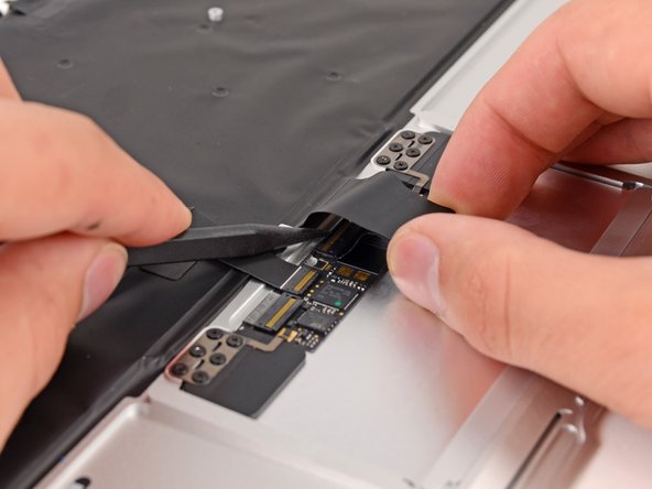
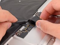
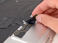
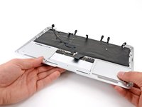
Push/lift the keyboard ribbon cable off of the upper case with one hand.
-
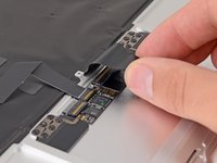
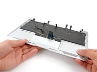
With the other hand, use a spudger to flip up the retaining flap on the ZIF connector.
-
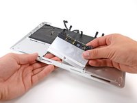
Once the retaining flap has been flipped up, carefully pull the ribbon cable straight out of its socket.
-
-
-
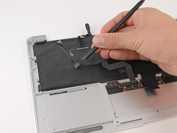
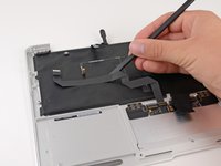
Use the flat end of a spudger to separate the trackpad ribbon cable from the underside of the keyboard.
-
-
-
Remove the six 1.5 mm Phillips #00 screws securing the trackpad to the upper case.
-
Check your replacement upper case—if it doesn't have this wide T5 screw, remove it to transfer into the replacement.
-
-
-
Holding the upper case up off the table with one hand, gently push the trackpad up through the upper case.
-
Remove the trackpad from the upper case.
-


To reassemble your device, follow these instructions in reverse order.
To reassemble your device, follow these instructions in reverse order.
crwdns2935221:0crwdne2935221:0
crwdns2935229:022crwdne2935229:0

crwdns2947412:08crwdne2947412:0
This is an excellent guide, thank you! I used it in combination with the procedure at http://www.insidemylaptop.com/replacing-... to replace a keyboard after water damage. The only issue I had was with that second procedure sealing the black backer film around the keyboard upon reassembly. There is a little light leakage but not terrible. Thanks again Andrew for this fantastic guide.
Impossible without this guide!
Great! Thank you!
A superb guide…….went like clockwork…….got it all done in about an hour and a half……I’m sure anyone could do it faster with this guide, but I double checked myself each step of the way. Thanks for posting this!
Dave
Replaced my keyboard and everything works fine except my “0” key and of course I need that to log in. I purchased the keyboard from Ifixit.com