crwdns2915892:0crwdne2915892:0
Use this guide to replace a damaged logic board.
crwdns2942213:0crwdne2942213:0
-
crwdns2935267:0crwdne2935267:0P5 Pentalobe Screwdriver Retina MacBook Pro and Air$5.99
-
Remove the following ten screws:
-
Two 8 mm 5-point Pentalobe screws
-
Eight 2.5 mm 5-point Pentalobe screws
-
-
-
Wedge your fingers between the display and the lower case and pull upward to pop the lower case off the Air.
-
-
-
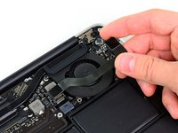
Use the flat end of a spudger to pry both short sides of the battery connector upward to disconnect it from its socket on the logic board.
-
Bend the battery cable slightly away from the logic board so the connector will not accidentally contact its socket.
-
-
-
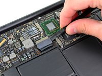
Remove the single 2.9 mm T5 Torx screw securing the SSD to the logic board.
-
-
-
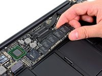
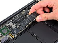
Use a spudger to help lift the free end of the SSD just enough to grab it with your other hand.
-
Pull the drive straight out of its socket and remove it from the logic board.
-
-
-
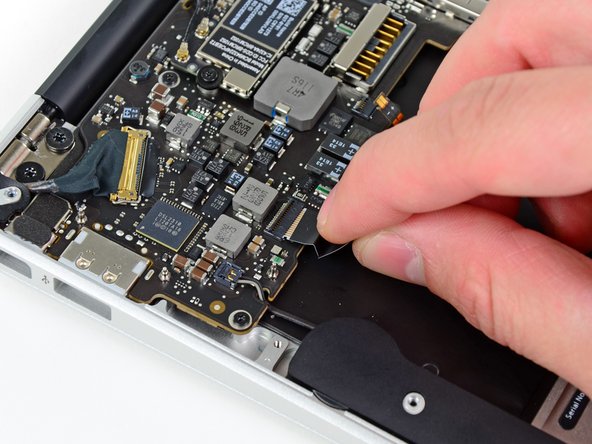
Use the flat end of a spudger to pry the I/O board cable up from its socket on the I/O board.
-
-
-
Peel the I/O board cable up from the adhesive securing it to the fan.
-
-
-
Use the flat end of a spudger to lift the I/O board connector up and out of its socket on the logic board
-
Remove the I/O board cable.
-
-
-
Use the tip of a spudger to carefully flip up the retaining flap on the fan cable ZIF socket.
-
-
-
Remove the following three screws securing the fan to the upper case:
-
Two 5.2 mm T5 Torx screws
-
One 3.6 mm T5 Torx screw
-
-
-
-
Lift the fan out of the upper case and carefully pull the fan ribbon cable out of its socket as you remove it from the Air.
-
-
-
Remove the following five screws securing the battery to the upper case:
-
Two 5.2 mm T5 Torx screws
-
One 6 mm T5 Torx screw
-
Two 2.6 mm T5 Torx screws
-
-
-
Lift the battery from its edge nearest the logic board and remove it from the upper case.
-
-
-
Use the flat end of a spudger to free the adhesive loop securing the I/O board power cable to the upper case.
-
Disconnect the I/O board by pulling the power cable away from its socket on the logic board.
-
-
-
Use the tip of a spudger to flip up the retaining flap on the keyboard backlight ribbon cable ZIF socket.
-
Pull the keyboard backlight ribbon cable out of its socket.
-
-
-
Use the tip of a spudger or your fingernail to flip up the retaining flap on the trackpad ribbon cable ZIF socket.
-
Pull the trackpad ribbon cable straight out of its socket toward the front edge of the Air.
-
-
-
Use the tip of a spudger to de-route the right speaker cable from the slot cut into the logic board.
-
-
-
Use the flat end of a spudger to pry the right speaker cable connector up and out of its socket on the logic board.
-
-
-
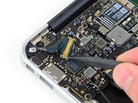
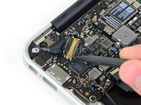
Gently push the tip of a spudger under the black plastic flap stuck to the display data cable lock to make the lock pop upward and away from the socket.
-
Remove the small rubber gasket from the corner of the upper case near the display data cable.
-
-
-
While holding the lock away from the socket, gently pull the display data cable out of its socket.
-
-
-
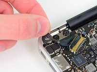
Use the flat end of a spudger to pry both antenna cable connectors up and off their sockets on the AirPort/Bluetooth card.
-
-
-
Gently de-route the antenna cables from the slot cut into the logic board.
-
-
-
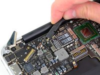
Remove the three 3.6 mm T5 Torx screws securing the logic board to the upper case.
-
-
-
Gently lift the logic board assembly out of the upper case, minding the fragile heat sink and any cables that may get caught.
-
-
-
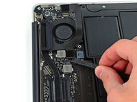
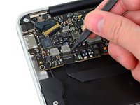
Remove the single 2.9 mm T5 Torx screw securing the AirPort/Bluetooth card to the logic board.
-
-
-
Slightly lift the free end of the AirPort/Bluetooth board and pull it out of its socket on the logic board.
-
Remove the AirPort/Bluetooth board from the logic board.
-
-
-
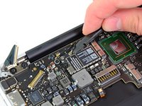
Remove the four 2.5 mm T5 Torx screws securing the heat sink to the logic board.
-
-
-
Remove the heat sink from the logic board.
-
Logic board remains.
-


To reassemble your device, follow these instructions in reverse order.
crwdns2935221:0crwdne2935221:0
crwdns2935229:029crwdne2935229:0

crwdns2947412:02crwdne2947412:0
Just for your information, this guide is not for the A1465 because the motherboard they are showing is from an A1370. The touchpad and touchpad flex cable are different in both models.
I concur this does not match the A1465 board in some areas. The Airport / Bluetooth connectors are in a different spot and the heatsink is different. Perhaps some photos from another board were used in a few places. The rest appears to be the same, so far.