crwdns2915892:0crwdne2915892:0
Use this guide to replace a cracked or broken display.
crwdns2942213:0crwdne2942213:0
-
crwdns2935267:0crwdne2935267:0P5 Pentalobe Screwdriver Retina MacBook Pro and Air$5.99
-
Remove the following ten screws:
-
Two 8 mm 5-point Pentalobe screws
-
Eight 2.5 mm 5-point Pentalobe screws
 crwdns2952109:0crwdne2952109:0
-
-
-
Wedge your fingers between the display and the lower case and pull upward to pop the lower case off the Air.
-
-
-
Use the flat end of a spudger to pry both short sides of the battery connector upward to disconnect it from its socket on the logic board.
-
Bend the battery cable slightly away from the logic board so the connector will not accidentally contact its socket.
-
-
-
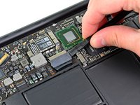
Remove the single 2.9 mm T5 Torx screw securing the SSD to the logic board.
-
-
-
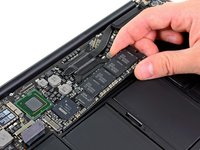
Use a spudger to help lift the free end of the SSD just enough to grab it with your other hand.
-
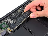
Pull the drive straight out of its socket and remove it from the logic board.
-
-
-
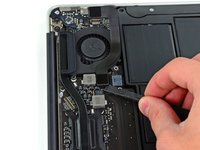
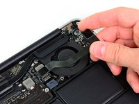
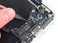
Use the flat end of a spudger to pry the I/O board cable up from its socket on the I/O board.
-
-
-
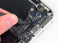
Peel the I/O board cable up from the adhesive securing it to the fan.
-
-
-
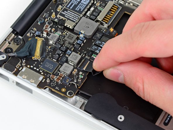
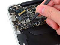
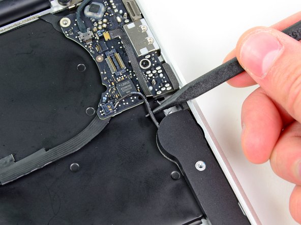
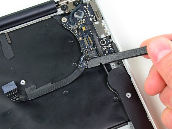
Use the flat end of a spudger to lift the I/O board connector up and out of its socket on the logic board
-
Remove the I/O board cable.
-
-
-
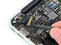
Use the tip of a spudger to carefully flip up the retaining flap on the fan cable ZIF socket.
-
-
-
Remove the following three screws securing the fan to the upper case:
-
Two 5.2 mm T5 Torx screws
-
One 3.6 mm T5 Torx screw
-
-
-
Lift the fan out of the upper case and carefully pull the fan ribbon cable out of its socket as you remove it from the Air.
-
-
-
Remove the following five screws securing the battery to the upper case:
-
Two 5.2 mm T5 Torx screws
-
One 6 mm T5 Torx screw
-
Two 2.6 mm T5 Torx screws
-
-
-
-
Lift the battery from its edge nearest the logic board and remove it from the upper case.
-
-
-
Use the flat end of a spudger to free the adhesive loop securing the I/O board power cable to the upper case.
-
Disconnect the I/O board by pulling the power cable away from its socket on the logic board.
-
-
-
Use the tip of a spudger to flip up the retaining flap on the keyboard backlight ribbon cable ZIF socket.
-
Pull the keyboard backlight ribbon cable out of its socket.
-
-
-
Use the tip of a spudger or your fingernail to flip up the retaining flap on the trackpad ribbon cable ZIF socket.
-
Pull the trackpad ribbon cable straight out of its socket toward the front edge of the Air.
-
-
-
Use the tip of a spudger to de-route the right speaker cable from the slot cut into the logic board.
-
-
-
Use the flat end of a spudger to pry the right speaker cable connector up and out of its socket on the logic board.
-
-
-
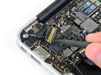
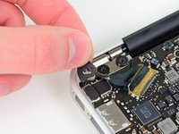
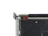
Gently push the tip of a spudger under the black plastic flap stuck to the display data cable lock to make the lock pop upward and away from the socket.
-
Remove the small rubber gasket from the corner of the upper case near the display data cable.
-
-
-
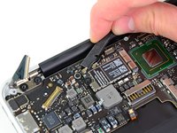
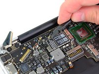
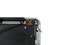
While holding the lock away from the socket, gently pull the display data cable out of its socket.
-
-
-
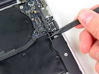
Use the flat end of a spudger to pry both antenna cable connectors up and off their sockets on the AirPort/Bluetooth card.
-
-
-
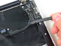
Gently de-route the antenna cables from the slot cut into the logic board.
-
-
-
Remove the three 3.6 mm T5 Torx screws securing the logic board to the upper case.
-
-
-
Gently lift the logic board assembly out of the upper case, minding the fragile heat sink and any cables that may get caught.
-
-
-
Remove the small rubber gasket from the corner of the upper case nearest the I/O board.
-
-
-
Use the tip of a spudger to carefully flip up the retaining flap on the microphone cable ZIF socket.
-
Pull the microphone ribbon cable straight out of its socket.
-
-
-
De-route the left speaker cable from the notch cut into the I/O board.
-
Use the flat end of a spudger to pry the left speaker cable connector up and out of its socket on the I/O board.
-
-
-
Pull the camera cable parallel to the face of the I/O board toward the rear edge of the Air to disconnect it from its socket.
-
-
-
Remove the single 3.6 mm T5 Torx screw securing the I/O board to the upper case.
-
-
-
Carefully lift the I/O board from its edge nearest the logic board and remove it from the upper case.
-
-
-
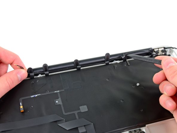
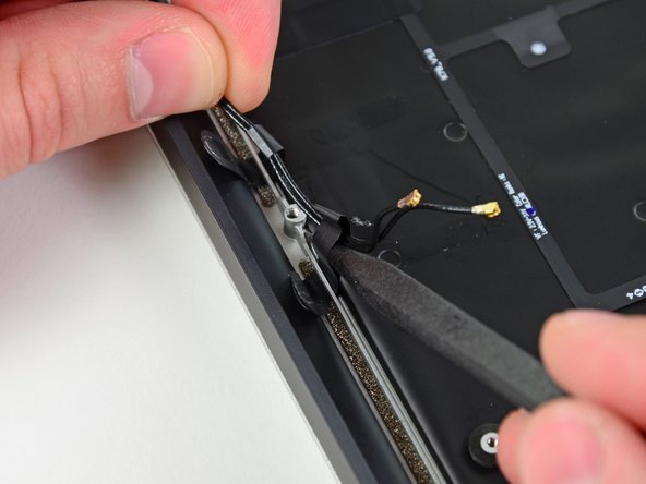
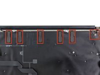
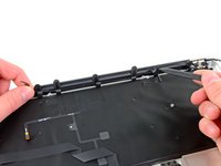
Peel up the six cable loops securing the antenna cables to the upper case.
-
Gently pull the cable loops slightly out of the channel cut into the upper case one at a time.
-
Use your spudger to open up the plastic loops as you de-route the antenna cables through them.
-
Repeat this for all of the retaining loops.
-
-
-
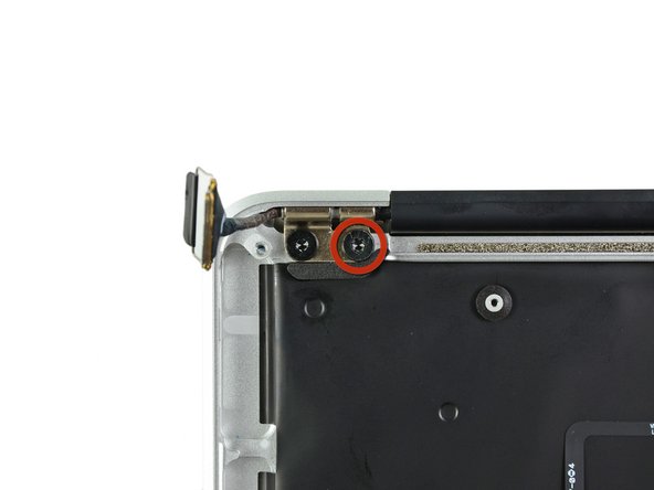
Remove the inner 4.9 mm T8 Torx screw securing each display hinge to the upper case (two screws total).
-
-
-
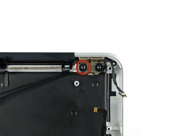
Open the display until it is perpendicular to the upper case and place it on a table as shown.
-
While holding the Air steady, remove the remaining 4.9 mm T8 Torx screw from the lower display bracket.
-
-
-
Remove the last 4.9 mm T8 Torx screw securing the display to the upper case.
-
-
-
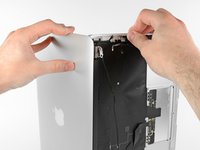
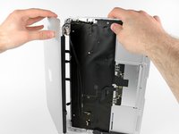
Push the upper case slightly toward the display assembly, then rotate it away from the front of the display assembly.
-
Once the two display hinges have cleared the upper case, remove the display and set it aside.
-


To reassemble your device, follow these instructions in reverse order.
crwdns2935221:0crwdne2935221:0
crwdns2935229:047crwdne2935229:0


crwdns2947412:06crwdne2947412:0
Amazing guide, finished in under 3 hours for less than $300!
sillemleatea - crwdns2934203:0crwdne2934203:0 crwdns2950251:0crwdne2950251:0
Step 21, be careful when de-routing the wifi cables. Ensure they are Well away from the logic board when you remove it. The connectors appear to be little more than pushed onto the aerial wires and they can become EASILY separated from the cables if not fully pulled AWAY.
YOU HAVE BEEN WARNED!
Pete B - crwdns2934203:0crwdne2934203:0 crwdns2950251:0crwdne2950251:0
Yep! I was warned but managed to pull one off anyway!Why are they so impossible to put back on? I bought a replacement cable and swapped them over. Getting that bezel off was a little stressful.
But thanks A Goldberg for the guide. Invaluable.
Andy Hannen - crwdns2934203:0crwdne2934203:0 crwdns2950251:0crwdne2950251:0
Hello Andrew, congratulations for the amazing guide! Wonderful job!
I need help trying to understand what's happening with a similar model which turns on only when he wants :)
I disassembled all of it and found nothing wrong, although it still shows the same behaviour. When it turns on (rarely), it works pretty fine, but randomly reboots sometimes. I suspect that there's something wrong with the switch key inside the display part, with some faulty electrical contact. I was trying to remove the black plastic bar below the "MacBook Air" label, but it seems to break if I force it.
My questions are: How can I remove this black bar without breaking it? Is it possible instead to remove first one of the display hinges to remove the black bar by sliding it to the side? Is there any way at all to make sure that the problem is not with the switch key inside it? Unfortunatelly I don't have a spare display to test it :(
I know it can be difficult to solve, but I appreciate any help if you have!
Thanks in advance!
Marcio Tavares - crwdns2934203:0crwdne2934203:0 crwdns2950251:0crwdne2950251:0
So, I found this mac in an e-waste pile, and the display is broken. Handling 10.7 drivers, and I want to get the screen back... Although Macs are all about pretty (and I like pretty, too), if I'm not looking for pretty, and I can just put the screen on top of the broken one, can't I just unplug the data cable for the LCD, plug the new one back in and then do everything I need to do? Two screens isn't *half* as bad as one. I'm just asking to sum it up, remove data cable to screen one, attach it to another working screen, and bam? No? Yes? Plz, I really want to know. Alternatively, someone please write a guide on how to remotely make a monitor mirror a screen? That would be great! And thanks to the people that understood my subtle joke.
Revolver265 - crwdns2934203:0crwdne2934203:0 crwdns2950251:0crwdne2950251:0