crwdns2915892:0crwdne2915892:0
Internal prerequisite.
crwdns2942213:0crwdne2942213:0
-
-
Disconnect the I/O board by pulling the power cable away from its socket on the logic board.
-
-
-
Use the tip of a spudger or your fingernail to flip up the retaining flap on the trackpad ribbon cable ZIF socket.
-
Pull the trackpad ribbon cable straight out of its socket toward the front edge of the Air.
-
-
-
Use the tip of a spudger to de-route the right speaker cable from the slot cut into the logic board.
-
-
-
Use the flat end of a spudger to pry the right speaker cable connector up and out of its socket on the logic board.
-
-
-
-
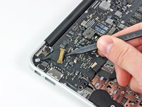
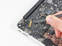
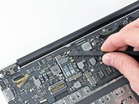
Gently push the tip of a spudger under the black plastic flap stuck to the display data cable lock to make the lock pop upward and away from the socket.
-
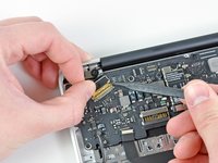
While holding the lock away from the socket, use the tip of a spudger and your fingers to gently remove the display data cable from its socket.
-
-
-
Remove the small rubber gasket from the corner of the upper case near the display data cable.
-
-
-
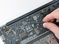
Use the flat end of a spudger to pry both antenna cable connectors up and off their sockets on the AirPort/Bluetooth card.
-
-
-
Gently de-route the antenna cables from the slot cut into the logic board.
-
-
-
Remove the three 3.6 mm T5 Torx screws securing the logic board to the upper case.
-
-
-
Gently lift the logic board assembly out of the upper case, minding the fragile heat sink and any cables that may get caught.
-


To reassemble your device, follow these instructions in reverse order.
To reassemble your device, follow these instructions in reverse order.
