crwdns2915892:0crwdne2915892:0
Use this guide to replace the I/O board, home to the MagSafe 2, USB, and headphone ports.
crwdns2942213:0crwdne2942213:0
-
crwdns2935267:0crwdne2935267:0P5 Pentalobe Screwdriver Retina MacBook Pro and Air$5.99
-
Remove the following ten screws:
-
Two 8 mm 5-point Pentalobe screws
-
Eight 2.5 mm 5-point Pentalobe screws
-
-
-
Wedge your fingers between the display and the lower case and pull upward to pop the lower case off the Air.
-
-
-
Use the flat end of a spudger to pry both short sides of the battery connector upward to disconnect it from its socket on the logic board.
-
Bend the battery cable slightly away from the logic board so the connector will not accidentally bend back and make contact with its socket.
-
-
-
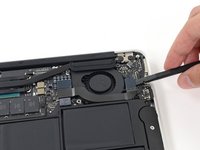
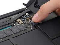
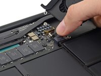
Use the flat end of a spudger to pry the left and right I/O board cable connectors up off their respective sockets on the I/O board.
-
-
-
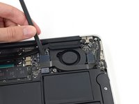
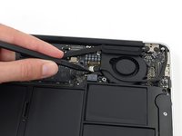
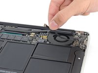
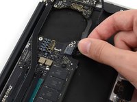
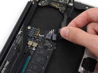
Use the tip of a spudger to carefully push on each side of the iSight camera cable connector to loosen it out of its socket on the logic board.
-
-
-
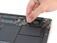
Peel the iSight camera cable up off the adhesive securing it to the fan.
-
-
-
-
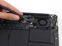
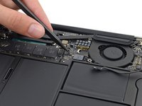
Use the tip of a spudger to carefully flip up the retaining flap on the fan cable ZIF socket.
-
-
-
Remove the following three screws securing the fan to the upper case:
-
Two 5.5 mm T5 Torx screws
-
One 4.6 mm T5 Torx screw
-
-
-
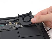
Lift, but do not remove the fan out of its recess in the upper case.
-
Carefully pull the fan ribbon cable out of its socket as you remove the fan from the Air.
-
-
-
Remove the following five screws securing the battery to the upper case:
-
Two 5.2 mm T5 Torx screws
-
One 6 mm T5 Torx screw
-
Two 2.6 mm T5 Torx screws
-
-
-
Lift the battery from its edge nearest the logic board and remove it from the upper case.
-
-
-
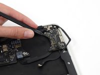
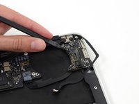
Disconnect the I/O board power cable from the logic board by pulling the cable out of its socket on the logic board.
-
-
crwdns2935267:0crwdne2935267:0Tweezers$4.99
-
-
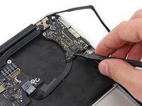
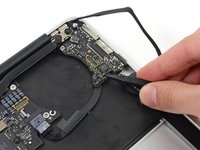
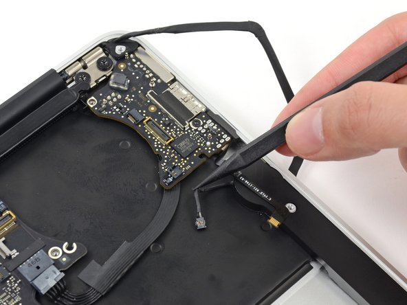
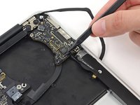
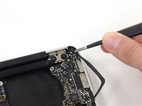
Use the tip of a spudger to carefully flip up the retaining flap on the microphone cable ZIF socket.
-
Pull the microphone ribbon cable straight out of its socket.
-
-
-
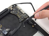
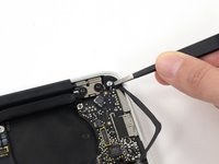
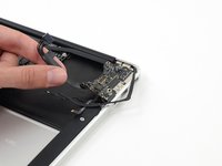
Use the tip of a spudger to pry under the speaker cable near the connector to lift the connector straight up out of its socket.
-
-
-
De-route the cable from its notch in the I/O board.
-
-
-
Remove the small rubber gasket from the corner of the upper case nearest the I/O board.
-
-
-
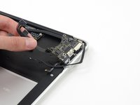
Remove the single 3.6 mm T5 Torx screw securing the I/O board to the upper case.
-
In some models this is a 3.1 mm T5 Torx screw.
-
-
-
Carefully lift the I/O board by its power cable and pull it away from the edge of the case.
-


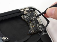
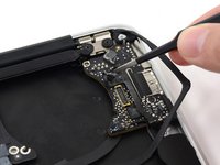

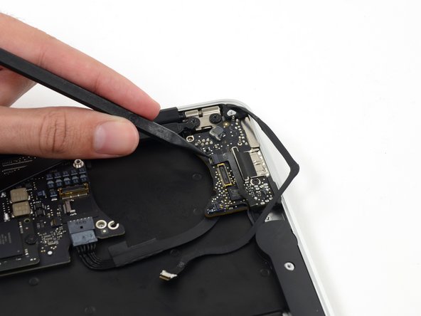
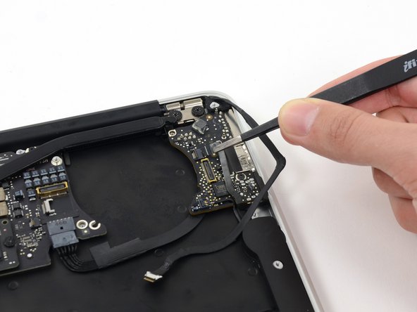


To reassemble your device, follow these instructions in reverse order.
crwdns2935221:0crwdne2935221:0
crwdns2935229:011crwdne2935229:0

