crwdns2915892:0crwdne2915892:0
Use this guide to replace a cracked or faulty display assembly in your MacBook Air.
crwdns2942213:0crwdne2942213:0
-
crwdns2935267:0crwdne2935267:0P5 Pentalobe Screwdriver Retina MacBook Pro and Air$5.99
-
Remove the following ten screws:
-
Two 8 mm 5-point Pentalobe screws
-
Eight 2.5 mm 5-point Pentalobe screws
 crwdns2952109:0crwdne2952109:0
-
-
-
Wedge your fingers between the display and the lower case and pull upward to pop the lower case off the Air.
-
-
-
Use the flat end of a spudger to pry both short sides of the battery connector upward to disconnect it from its socket on the logic board.
-
Bend the battery cable slightly away from the logic board so the connector will not accidentally bend back and make contact with its socket.
-
-
-
Use the flat end of a spudger to pry the left and right I/O board cable connectors up off their respective sockets on the I/O board.
-
-
-
Lift and remove the I/O board cable.
-
-
-
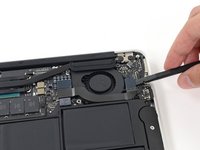
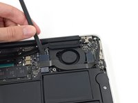
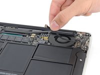
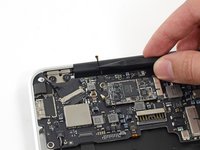
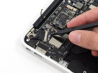
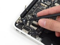
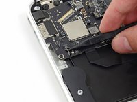
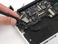
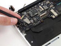
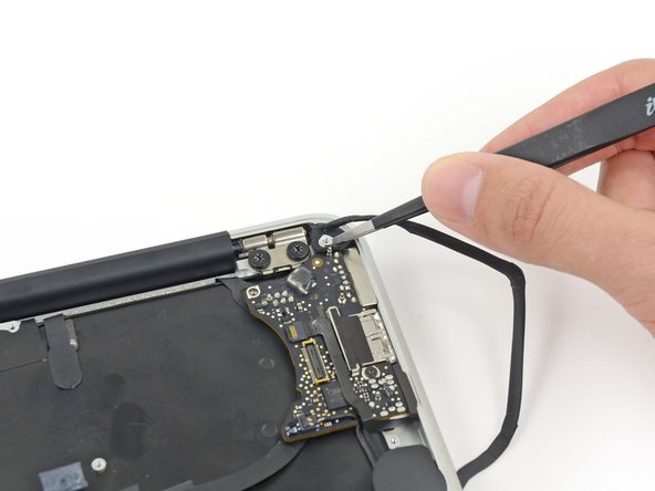
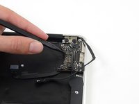
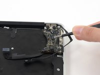
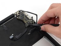
Use the tip of a spudger to carefully push on each side of the iSight camera cable connector to loosen it out of its socket on the logic board.
-
-
-
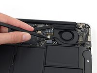
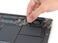
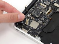
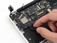
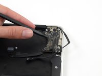
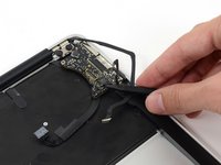
Peel the iSight camera cable up off the adhesive securing it to the fan.
-
-
-
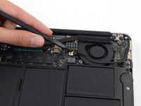
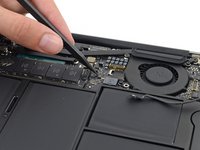
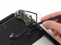
Use the tip of a spudger to carefully flip up the retaining flap on the fan cable ZIF socket.
-
-
-
Remove the following three screws securing the fan to the upper case:
-
Two 5.5 mm T5 Torx screws
-
One 4.6 mm T5 Torx screw
-
-
-
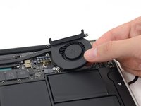
Lift, but do not remove the fan out of its recess in the upper case.
-
Carefully pull the fan ribbon cable out of its socket as you remove the fan from the Air.
-
-
-
Use the flat end of a spudger to pry both antenna connectors up from their sockets on the AirPort/Bluetooth card, and move them out of the way.
-
-
-
Remove the following five screws securing the battery to the upper case:
-
Two 5.2 mm T5 Torx screws
-
One 6 mm T5 Torx screw
-
Two 2.6 mm T5 Torx screws
-
-
-
-
Lift the battery from its edge nearest the logic board and remove it from the upper case.
-
-
-
Disconnect the I/O board by pulling the power cable away from its socket on the logic board.
-
-
-
Use the tip of a spudger to de-route the antenna cables from their notches in the logic board.
-
-
-
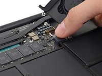
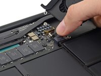
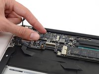
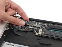
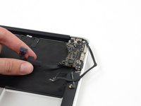
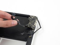
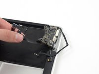
Gently push the tip of a spudger under the black plastic flap stuck to the display data cable lock to make the lock pop upward and away from the socket.
-
While holding the lock away from the socket, gently pull the display data cable out of its socket.
-
-
-
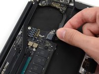
Use the tip of a spudger to pry under the speaker cable connector, lifting it straight up from its socket.
-
De-route the cable from its notch in the logic board.
-
-
-
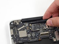
Use the tip of a spudger or your fingernail to flip up the retaining flap on the trackpad ribbon cable ZIF socket.
-
Pull the trackpad ribbon cable straight out of its socket toward the front edge of the Air.
-
-
-
Use the tip of a spudger to flip up the retaining flap on the keyboard backlight ribbon cable ZIF socket.
-
Pull the keyboard backlight ribbon cable out of its socket.
-
-
-
Remove the single 2.9 mm T5 Torx screw securing the AirPort/Bluetooth card to the logic board.
-
-
-
Slightly lift the free end of the AirPort/Bluetooth board and pull it out of its socket on the logic board.
-
-
-
Remove the three 3.6 mm T5 Torx screws securing the logic board to the upper case.
-
In some models these are 3.1 mm T5 Torx screws.
-
-
-
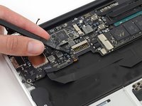
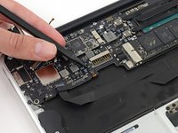
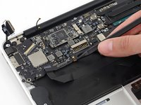
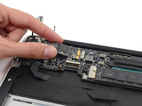
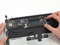
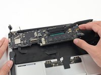
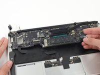
Gently lift the logic board assembly from the heat sink end and pull it away from the port side of the case to remove it from the Air.
-
-
-
Remove the small rubber gasket from the corner of the upper case nearest the the I/O board.
-
Remove the gasket from the corner nearest display cable connector.
-
-
crwdns2935267:0crwdne2935267:0Tweezers$4.99
-
-
Use the tip of a spudger to carefully flip up the retaining flap on the microphone cable ZIF socket.
-
With a pair of tweezers, pull the microphone ribbon cable straight out of its socket.
-
-
-
Use the tip of a spudger to pry under the speaker cable near the connector, lifting it straight up from its socket.
-
De-route the cable from its notch in the logic board.
-
-
-
Remove the single 3.6 mm T5 Torx screw securing the I/O board to the upper case.
-
-
-
Carefully lift the I/O board by its power cable and pull it away from the edge of the case.
-
-
-
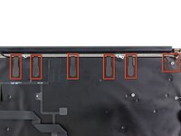
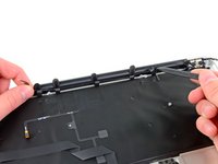
Peel up the six cable loops securing the antenna cables to the upper case.
-
Gently pull the cable loops slightly out of the channel cut into the upper case one at a time.
-
Use your spudger to open up the plastic loops as you de-route the antenna cables through them.
-
-
-
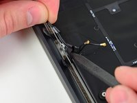
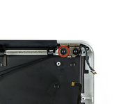
Remove the inner 4.9 mm T8 Torx screw securing each display hinge to the upper case (two screws total).
-
-
-
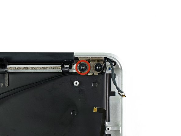
While holding the Air steady, remove the remaining 4.9 mm T8 Torx screw from the lower display bracket.
-
-
-
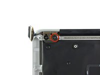
Remove the last 4.9 mm T8 Torx screw securing the display to the upper case.
-
-
-
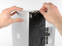
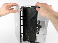
Push the upper case slightly toward the display assembly, then rotate it away from the front of the display assembly.
-
Once the two display hinges have cleared the upper case, remove the display.
-


To reassemble your device, follow these instructions in reverse order.
crwdns2935221:0crwdne2935221:0
crwdns2935229:021crwdne2935229:0

crwdns2947412:04crwdne2947412:0
anyone know if this uses the same display as the mid 2013 model?
Scott - crwdns2934203:0crwdne2934203:0 crwdns2950251:0crwdne2950251:0
This is great, but how do I now replace the screen inside the display assembly?
Gary Ogilvie - crwdns2934203:0crwdne2934203:0 crwdns2950251:0crwdne2950251:0
The use of adhesive and backing materials would likely make this unattenable and cost prohibitive assuming you could even find the after-market subassembly parts. I removed my broken LCD and made a wall clock from the metal exterior. More power to you if you try. My suggestion, if you find all the parts, would be to run the edge with a utility knife - you will likely nick the antenna cables so those will need to be rerun. Then heat-gun the back aluminum case (avoid the logo) and pry out the LCD with a narrow (and SHARPENED) 2.5” or less putty knife being carful of the plastic backing. If the heat-gun worked the LCD may come out without shattering. Reverse the process if you have the parts. The cable routing will be a chore. Parts might include Antenna Cable, LVDS cable, LCD, propriety backing, adhesive, and something to replace the edging that ran between the LCD and aluminum frame.
Jeff - crwdns2934203:0crwdne2934203:0 crwdns2950251:0crwdne2950251:0
Terrific guide, every step is explained and displayed with such clarity and precision. Thank you for this, saved my MacBook!
Trinity Coyle - crwdns2934203:0crwdne2934203:0 crwdns2950251:0crwdne2950251:0