crwdns2915892:0crwdne2915892:0
This guide will show you how to replace the logic board.
crwdns2942213:0crwdne2942213:0
-
-
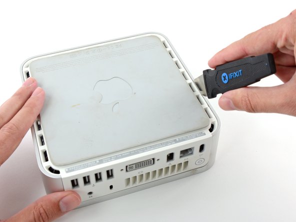
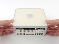
Power down your Mac mini, disconnect all of the cables, and flip it over.
-
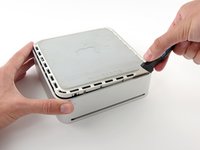
Insert the Jimmy into the crack between the aluminum top housing and the plastic lower housing.
-
The Jimmy should reach a stop about 3/8" down.
-
-
-
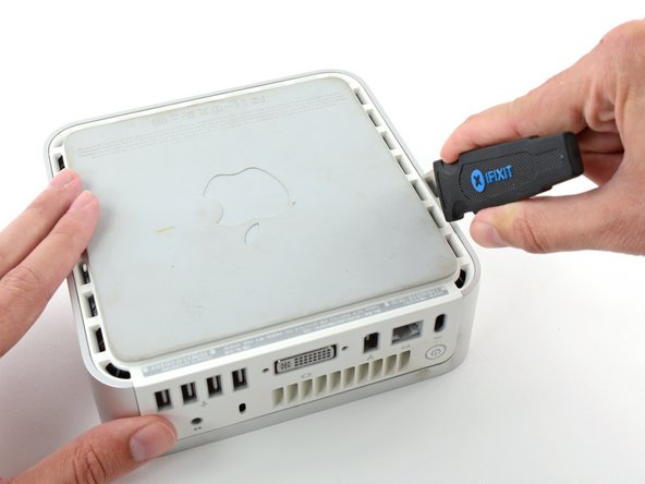
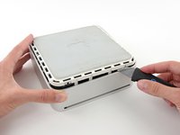
Gently bend the Jimmy outwards to pry the crack open a little larger and lift the lower housing up a small amount.
Patience is your best friend.
Do not insert “jimmy in too far. Marking a line from tip upwards on the tool will prevent too far insertion, possibly breaking tabs or damaging internal components.
To prevent the cover closing back up, small strips of matchbook cover (os equivalent) can be inserted about half inch hold prevent closure.
I think it needs to be made more clear that what you want to be doing is applying upward pressure on the back I/O panel with your HAND while pressing the clips with the jimmy, sort of like tensioning a lock and then setting individual tumblers. (Yeah, I watch LockPickingLawyer.)
The pictures appear to show trying to lift the lower housing using the jimmy, similar to how I've seen people doing things like prying with a putty knife or screwdriver... and that plastic is only going to get more brittle over time.
If you apply the upward pressure with your hand via the back panel and then work your way around the outside edge clip-by-clip, then it's much easier to be gentle with the jimmy because your only goal is to press on each clip enough to release it. All the rest of the force comes from, say, a finger hooked into the edge of the Ethernet port and a thumb pressing on the edge of the top cover.
-
-
-
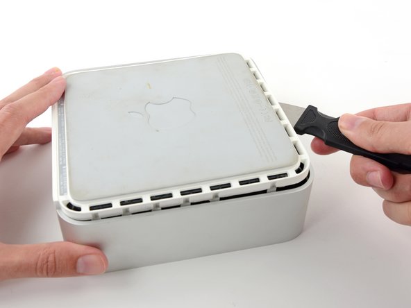
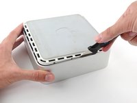
Once you have the first side free, rotate the Mac mini and start prying up on the front edge.
-
Use the same prying motion to both bend the clips inward and lift the lower housing up out of the top housing.
-
-
-
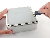
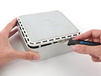
You may need to move the Jimmy along the edge to pry up all of the clips. Be patient and do a little bit at a time.
-
-
-
Keep working around the perimeter, freeing the clips along the final edge.
-
-
-
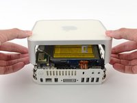
Flip the Mac mini back over and lift the top housing off of the lower housing.
Before reassembly, make sure no wires are sticking out.
Line up top cover carefully. Gently press down on top cover until top and bottom fully seated.
CAUTION! DO NOT PRESS TOO HARD ON THE COVER TO PREVENT CRACKING THE PLASTIC TOP.
GO EASY.
Re: reassembly, I found it gentler to use the jimmy to lightly press the plastic clips in a little bit to get them past catching on the frame with minimal force.
-
-
-
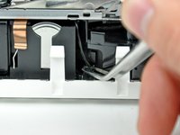
Slightly squeeze the two retaining arms toward each other and lift the AirPort antenna off its post.
How serious is it if W1 loses the spring? Mine pinged off and I cannot find it. I spent about half an hour looking with no success.
-
-
-
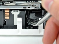
Use the tip of a spudger to slightly lift the left side of the ZIF cable lock up from its socket.
Now also lift the right side of the ZIF cable lock up from its socket.
Good catch of the incomplete unlocking instructions. ;P
Hmmm... what if I didn't read this before and I removed the cable and the lock sort of broke?... what would happen... would I experience problems? I can still put the cable back in place and push the lock back down with the spudger.
Same. I totally removed the lock , the edges are busted and won't stay in place, How can I get the cable to stay? what's the fix?
Suzanne -
Dan O & Suzanne, hold the cable in the socket and put a dab of hot glue on both sides, It's non-conductive and should hold...worked for me.
does any one know, where to get the connector from zhe ZIF Cable?
someone, that preowned my mac broke the holder!
Julian, did you ever find where to get a replacement lock for the Zip Cable. Mine is also broken..
Suzanne -
This is not my first memory replacement in a Mini and I got over-confident and stupidly fully removed the audio cable ZIF lock and assumed I had broken something. But, now that I have read this guide more carefully, I am not sure. I sure would love to hear some detailed instructions for putting a ZIF lock back on.
Is it possible that I have removed it without having broken it? If I have broken it, do I have to buy a new cable? Just a new ZIF lock? A new audio board? This is a 2.0 GHz A1176.
Thanks!
Michael, Mine seems to be broken. I bought & tried the Kapton Tape that was suggested & still no sound.
Suzanne -
C’est la première que je doit déverrouiller un câble ZIF. Je précise qu’il faut lever à gauche et à droite, ça force un peu, prendre appui sur le boitier du Mac, comme e montre la photo.
La partie noire reste dans la partie blanche (+1 mm), et la nappe flexible sort par le haut.
-
-
-
-
Lift the audio board ribbon cable up out of its socket.
As an option to avoid potential damage when disconnecting the cable from the ZIF socket and clip, it is possible to unscrew the audio board and remove it along with the internal frame.
-
-
crwdns2935267:0crwdne2935267:0Tweezers$4.99
-
Use a pair of tweezers to lift the hard drive thermal sensor cable connector up off its socket on the logic board.
Managed to leave this connected by flopping back the drive rather than totally removing
WATCH OUT!!
separated one of the wires from the connector very easily. i would have preferred to use a spudger at this step. the tweezers in effect snipped the wire!!
As my experience you should definitely use angeled tweezers as shown in several pictures. To avoid stripped cable deflash sharp edges of the tweezers a little bit. I never experienced problems when using that kind of tool carefully.
I've had to remove a few of these connectors on iBooks and other small Apple devices ... I've found that, with careful and gentle pressure (working first one side and then the other) using a small flat-headed jeweller's screwdriver is best.
I agree Mike.
Note where the airport antennae connecting wire comes out from the interior along the top. When reassembling, it has to be routed the same way, or it won't reach its install position.
If your fan runs at high speed after you complete this project, you have forgotten to reconnect the thermal sensor.
-
-
-
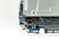
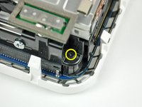
Remove the recessed Phillips screw near the power button securing the internal frame to the bottom housing.
-
-
-
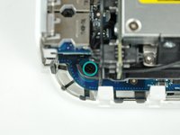
Remove the recessed Phillips screw near the sleep light securing the internal frame to the bottom housing.
-
-
-
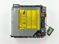
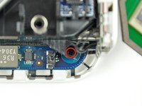
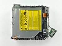
Remove the Phillips screw from the internal frame near the Bluetooth antenna.
Before removing any of these screws, there is another step needed which is not here:
On the front of the optical drive, right side as you look at the slot-load, is a small blue board attached by a single black screw. This needs to be removed before the optical drive can be taken out.
-
-
-
Remove the Phillips screw near the audio ports securing the internal frame to the bottom case.
On reassembly, if you don't have a magnetic screwdriver, a tiny dab of grease at the tip of your screwdriver will help hold the screw on the driver so you can lower it into the recessed slot.
-
-
-
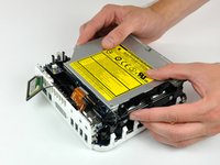
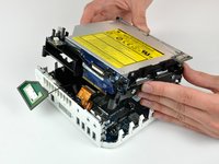
Gently lift the internal frame up from the bottom housing, minding the AirPort antenna and any other cables that may get caught.
At this point be careful that you don't pull out the Airport antenna ... but if you do, just check that it is back before re-assembling.
During re-assembly, the internal frame has to go in at an angle ... the back of the optical drive goes in first.
This means that you can seat the fan cover correctly, but more importantly, there is an interconnect board on the back of the optical drive that must be firmly pushed back into its housing on the logic board.
Reassembly: Before slipping the main frame back into its place, refer to earlier photos, ensuring proper routing of the WiFi cable.
If, like me, you pull the wire on the airport antenna free, it snaps back into place easily. The connector is on the extra card screwed to the motherboard that looks like it has a phone battery embedded in it. The connector is at the top of the 'battery'. This accessory card is the wifi card, so it makes sense that the antenna plugs onto this.
-
-
crwdns2935267:0crwdne2935267:0Tweezers$4.99
-
Firmly grasp the power button cable connector with a pair of tweezers and lift it straight up off the logic board.
-
-
-
Firmly grasp the sleep light cable connector with a pair of tweezers and lift it straight up off the logic board.
-
-
-
Remove the single T10 torx lug securing the logic board to the bottom housing.
I think a T15 fits better
Agreed, T15 is a better fit
-
-
-
Use the flat end of a spudger to slightly lift the logic board near the PRAM battery to separate it from the bottom housing.
-
-
-
Gently lift the free end of the logic board and wiggle the board as you pull it away from the I/O ports.
Hi, when re-assembling, if you find resistance to the board sliding right up to the rear panel make sure that the spring finger on the casing goes over the power connector not inside it. It fits much better that way!
-
-
-
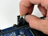
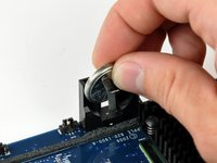
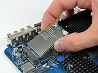
Push the PRAM battery toward the center of the logic board and pull it up out of its holder. You'll have to push the battery in further than you'd expect in order to get it to pop free.
-
When inserting the new battery, make sure the side with writing along the edges faces the black plastic holder. You should also ensure that the metal connectors make contact with the battery (you can bend them forward if they do not).
-
-
-
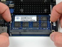
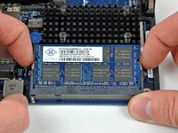
Simultaneously pull the tabs on each side of the RAM chip away from the center of the chip. These tabs lock the chip in place and releasing them will cause the chip to "pop" up.
-
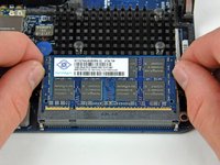
Pull the RAM chip directly out from its connector.
-
-
-
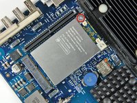
Use the flat end of a spudger to pry the AirPort antenna cable connector up off the AirPort card.
-
-
-
Remove the single Phillips screw securing the AirPort card to the logic board.
-
Pull the AirPort card away from its socket on the logic board.
-


To reassemble your device, follow these instructions in reverse order.
To reassemble your device, follow these instructions in reverse order.
crwdns2935221:0crwdne2935221:0
crwdns2935229:025crwdne2935229:0

crwdns2947410:01crwdne2947410:0
In step 18:
“Remove the single T10 torx lug securing the logic board to the bottom housing. “
This is not a T10 but a T15 torx.
A spackle knife makes these steps go much faster.
jouniseppanen - crwdns2934203:0crwdne2934203:0
A double sided letter opener or a thin non-serrated butter knife will suffice.
To prenent cosmetic blemishes, place a matchbook cover or similar thin cardboard on the outer perimeter under the “jimmy”.
Mike - crwdns2934203:0crwdne2934203:0
Despite mentioning recommended tools at the top I think it’s really worthwhile making a point about narrow Philips screwdrivers at this point before people start putting the case apart.
Matt D - crwdns2934203:0crwdne2934203:0