crwdns2915892:0crwdne2915892:0
This guide will show you how to replace the logic board.
crwdns2942213:0crwdne2942213:0
-
-
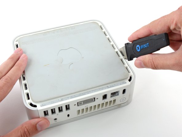
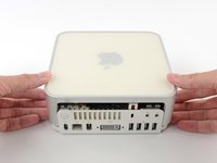
Power down your Mac mini, disconnect all of the cables, and flip it over.
-
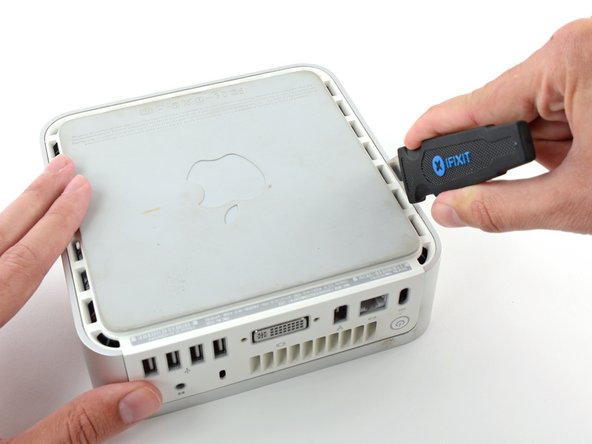
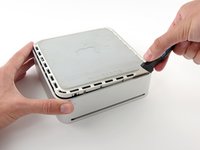
Insert the Jimmy into the crack between the aluminum top housing and the plastic lower housing.
-
The Jimmy should reach a stop about 3/8" down.
-
-
-
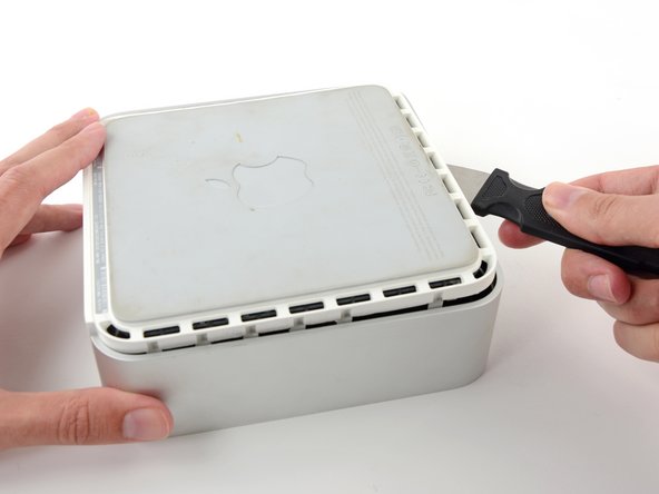
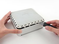
Gently bend the Jimmy outwards to pry the crack open a little larger and lift the lower housing up a small amount.
-
-
-
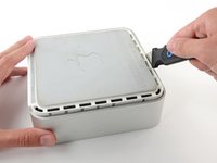
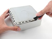
Once you have the first side free, rotate the Mac mini and start prying up on the front edge.
-
Use the same prying motion to both bend the clips inward and lift the lower housing up out of the top housing.
-
-
-
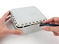
You may need to move the Jimmy along the edge to pry up all of the clips. Be patient and do a little bit at a time.
-
-
-
Keep working around the perimeter, freeing the clips along the final edge.
-
-
-
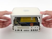
Flip the Mac mini back over and lift the top housing off of the lower housing.
-
-
-
Slightly squeeze the two retaining arms toward each other and lift the AirPort antenna off its post.
-
-
-
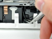
Use the tip of a spudger to slightly lift the left side of the ZIF cable lock up from its socket.
-
-
-
-
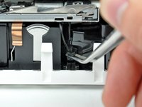
Lift the audio board ribbon cable up out of its socket.
-
-
crwdns2935267:0crwdne2935267:0Tweezers$4.99
-
Use a pair of tweezers to lift the hard drive thermal sensor cable connector up off its socket on the logic board.
-
-
-
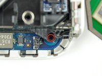
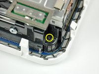
Remove the recessed Phillips screw near the power button securing the internal frame to the bottom housing.
-
-
-
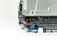
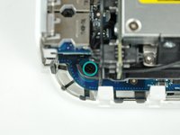
Remove the recessed Phillips screw near the sleep light securing the internal frame to the bottom housing.
-
-
-
Remove the Phillips screw from the internal frame near the Bluetooth antenna.
-
-
-
Remove the Phillips screw near the audio ports securing the internal frame to the bottom case.
-
-
-
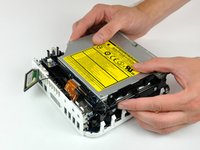
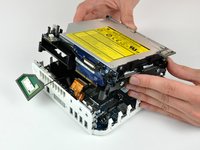
Gently lift the internal frame up from the bottom housing, minding the AirPort antenna and any other cables that may get caught.
-
-
crwdns2935267:0crwdne2935267:0Tweezers$4.99
-
Firmly grasp the power button cable connector with a pair of tweezers and lift it straight up off the logic board.
-
-
-
Firmly grasp the sleep light cable connector with a pair of tweezers and lift it straight up off the logic board.
-
-
-
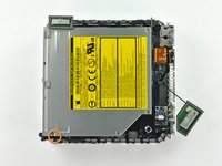
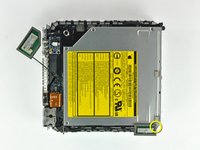
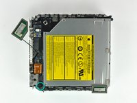
Remove the single T10 torx lug securing the logic board to the bottom housing.
-
-
-
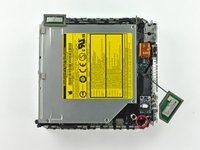
Use the flat end of a spudger to slightly lift the logic board near the PRAM battery to separate it from the bottom housing.
-
-
-
Gently lift the free end of the logic board and wiggle the board as you pull it away from the I/O ports.
-
-
-
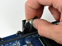
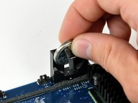
Push the PRAM battery toward the center of the logic board and pull it up out of its holder. You'll have to push the battery in further than you'd expect in order to get it to pop free.
-
When inserting the new battery, make sure the side with writing along the edges faces the black plastic holder. You should also ensure that the metal connectors make contact with the battery (you can bend them forward if they do not).
-
-
-
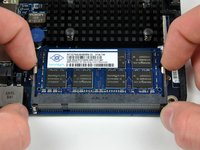
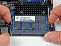
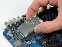
Simultaneously pull the tabs on each side of the RAM chip away from the center of the chip. These tabs lock the chip in place and releasing them will cause the chip to "pop" up.
-
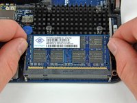
Pull the RAM chip directly out from its connector.
-
-
-
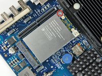
Use the flat end of a spudger to pry the AirPort antenna cable connector up off the AirPort card.
-
-
-
Remove the single Phillips screw securing the AirPort card to the logic board.
-
Pull the AirPort card away from its socket on the logic board.
-


To reassemble your device, follow these instructions in reverse order.
crwdns2935221:0crwdne2935221:0
crwdns2935229:025crwdne2935229:0

crwdns2947410:01crwdne2947410:0
In step 18:
“Remove the single T10 torx lug securing the logic board to the bottom housing. “
This is not a T10 but a T15 torx.