crwdns2915892:0crwdne2915892:0
Completely replacing the logic board requires removal of the logic board itself as well as all components attached to it.
crwdns2942213:0crwdne2942213:0
-
-
Place your thumbs in the depressions cut into the bottom cover.
-
Rotate the bottom cover counter-clockwise until the white dot painted on the bottom cover is aligned with the ring inscribed on the outer case.
-
-
-
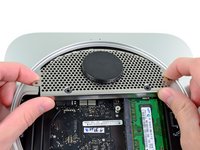
Tilt the mini enough to allow the bottom cover to fall away from the outer case.
-
Remove the bottom cover and set it aside.
-
-
-
Remove the two 11.3 mm T6 Torx screws securing the fan to the logic board near the antenna plate.
-
-
-
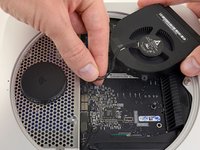
Lift the ear of the fan nearest the RAM up off the standoff secured to the outer case.
-
-
-
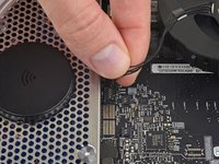
Lift the fan out of the mini for enough clearance to access its connector.
-
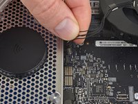
Grab all the wires at once and gently pull straight up to disconnect the fan from the logic board.
-
Remove the fan.
-
-
-
Remove the single 3.5 mm T6 Torx screw securing the cowling to the heat sink.
-
-
-
Lift the cowling from the end nearest the antenna plate.
-
Rotate the cowling away from the outer case and remove it from the mini.
-
-
-
Remove the following screws securing the antenna plate to the mini:
-
Two 6.6 mm T8 Torx screws
-
Two 5.0 mm T8 Torx or 2.0 mm Hex screws (either screwdriver will work)
-
When putting back together:
-
-
-
Slightly lift the antenna plate from the end closest to the RAM.
-
Carefully pull the antenna plate away from the circular rim of the outer case.
-
-
-
Use the tip of a spudger to carefully pry the antenna connector up from its socket on the AirPort/Bluetooth board.
-
-
-
-
Remove the antenna plate from the mini.
-
-
-
Use the flat end of a spudger to pry the hard drive connector up from its socket on the logic board.
-
-
-
Use the tip of a spudger to lift the IR sensor connector up and out of its socket on the logic board.
-
-
-
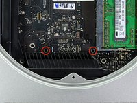
Remove the following three screws:
-
One 5.0 mm T8 Torx or 2.0 mm Hex screw (either screwdriver will work)
-
One 16.2 mm T6 Torx screw
-
One 26 mm T6 Torx standoff
-
-
crwdns2935267:0crwdne2935267:0Mac mini Logic Board Removal Tool$4.99
-
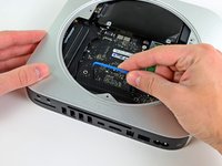
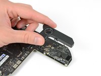
Insert the Mac mini Logic Board Removal Tool into the two holes highlighted in red. Be sure it makes contact with the top side of outer case below the logic board before proceeding.
-
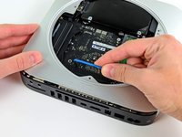
Carefully pull the tool toward the I/O board. The logic board and I/O board assembly should slightly slide out of the outer case.
-
Remove the Mac mini Logic Board Removal tool.
-
-
-
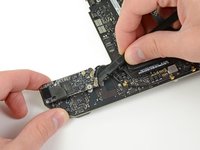
Pull the I/O board/logic board assembly out of the outer case enough to access the power connector.
-
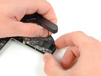
Use your fingers to disconnect the DC-In cable from the logic board.
-
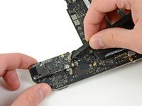
Pull the power cable connector toward the front side of the mini.
-
-
-
Carefully slide the logic board assembly out of the mini, minding any cables that may get caught.
-
-
-
Use the tip of a spudger to carefully pry the PRAM battery up and out of its holder on the logic board.
-
-
-
Remove the PRAM battery from the logic board.
-
-
-
Remove the following two screws securing the speaker to the logic board assembly:
-
One 3.5 mm T6 Torx screw
-
One 3.7 mm T6 Torx screw
-
-
-
Carefully lift the speaker wires upward to lift the speaker connector up and out of its socket on the logic board.
-
Lift and remove the speaker away from the logic board.
-
-
-
Use the flat end of a spudger to pry both antenna connectors up from their sockets on the AirPort/Bluetooth board.
-
-
-
Use your spudger to help disconnect the AirPort/Bluetooth ribbon cable from its socket on the AirPort/Bluetooth board.
-
-
-
Remove the two 2.6 mm T6 Torx screws securing the AirPort/Bluetooth board to the logic board.
-
-
-
Remove the AirPort/Bluetooth board from the logic board.
-
-
-
Use the flat end of a spudger to pry the AirPort/Bluetooth ribbon cable up off the logic board.
-
Remove the AirPort/Bluetooth ribbon cable.
-
-
-
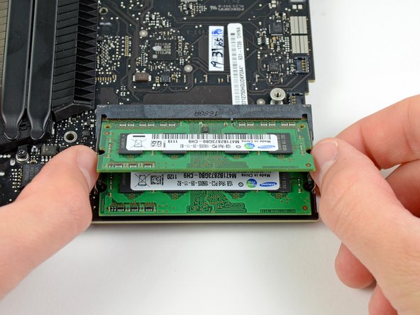
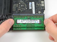
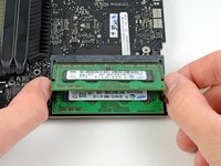
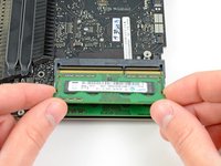
Release the tabs on each side of the RAM chip by simultaneously pushing each tab away from the chip.
-
After the RAM chip has popped up, pull it straight out of its socket.
-
-
-
Remove the single 5 mm T6 Torx standoff from the heat sink near the edge of the logic board.
-
-
-
Remove the following screws securing the heat sink to the logic board:
-
Four 8.6 mm T8 Torx screws
-
One 2.6 mm T6 Torx screw
-
-
-
Remove the heat sink from the logic board, minding any cables that may get caught.
-
Logic board remains.
-


To reassemble your device, follow these instructions in reverse order.
To reassemble your device, follow these instructions in reverse order.
crwdns2935221:0crwdne2935221:0
crwdns2935229:025crwdne2935229:0

crwdns2947412:07crwdne2947412:0
Can you replace the logic board in this Mac Mini Server, with one from the newer faster one, such as the 2012 2.6GHZ i7 server?
You absolutely can. My mid 2011 Mini logic board died, and I just had a 2012 board put in, which not only upgrades the USB ports to USB3, it also increases bus speed, although the slower RAM 1333 vs 1600 will still work fine.
I’m wanting to replace my 2011 Mac mini logic board with a 2012. I have a couple questions.
do you need to upgrade your power supply as well?
would the hard drive get formatted(meaning it’ll wipe the hard drive that has important information)?
thank you.
p.s. Dave posted about changing it with a 2014? Not sure if that’s a thing
Is it worth replacing the motherboard and can you get a replacement with an ungraded graphics chip as the 2011 integrated graphics was not designed for 2k or 4k?
It seems to be the only problem with my logic board and it already been burned torched once.
I realize this is an old post. But, I have a Mac Mini 2011 model that works fine, but can no longer update the IOS due to age. I was wondering if I am able to put something like a 2014 logic board in it?