crwdns2915892:0crwdne2915892:0
Completely replacing the logic board requires removal of the logic board itself as well as all components attached to it.
crwdns2942213:0crwdne2942213:0
-
-
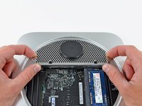
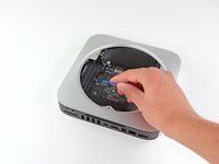
Place your thumbs in the depressions cut into the bottom cover.
-
Rotate the bottom cover counter-clockwise until the white dot painted on the bottom cover is aligned with the ring inscribed on the outer case.
 crwdns2952109:0crwdne2952109:0
-
-
-
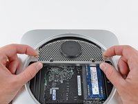
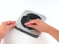
Tilt the mini enough to allow the bottom cover to fall away from the outer case.
-
Remove the bottom cover and set it aside.
-
-
-
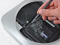
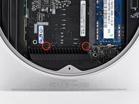
Remove the two 11.3 mm T6 Torx screws securing the fan to the logic board near the antenna plate.
-
-
-
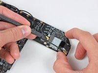
Lift the ear of the fan nearest the RAM up off the standoff secured to the outer case.
-
-
-
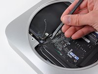
Lift the fan out of the mini for enough clearance to access its connector.
-
Carefully pull the fan cables upward to lift the fan connector up out of its socket on the logic board.
-
Remove the fan.
-
-
-
Remove the single 3.5 mm T6 Torx screw securing the cowling to the heat sink.
-
-
-
Lift the cowling from the end nearest the antenna plate.
-
Rotate the cowling away from the outer case and remove it from the mini.
-
-
-
Remove the following screws securing the antenna plate to the mini:
-
Two 6.6 mm T8 or T9 Torx screws
-
Two 5.0 mm T8 Torx or 2.0 mm Hex screws (either will work)
-
-
-
Slightly lift the antenna plate from the end closest to the RAM.
-
Carefully pull the antenna plate straight away from the circular rim of the outer case.
-
-
-
Use the tip of a spudger to carefully pry the antenna connector up off the AirPort/Bluetooth board.
-
-
-
Remove the antenna plate from the mini.
-
-
-
Remove the following three screws:
-
One 5.0 mm T8 Torx or 2.0 mm Hex screw (either will work)
-
One 16.2 mm T6 Torx screw
-
One 26 mm T6 Torx standoff
-
-
-
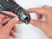
Carefully pull the wires for both hard drive thermal sensors upward to lift their connectors up and out of the sockets on the logic board.
-
-
-
-
Use the flat end of a spudger to pry both the hard drive and optical drive connectors up out of their sockets on the logic board.
-
-
-
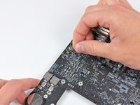
To disconnect the optical drive thermal sensor, pinch its cables between your thumb and a spudger and pry the spudger upward to lift the connector up and out of its socket on the logic board.
-
-
-
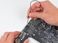
Use the tip of a spudger to lift the IR sensor connector up and out of its socket on the logic board.
-
-
crwdns2935267:0crwdne2935267:0Mac mini Logic Board Removal Tool$4.99
-
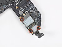
Insert a Mac mini Logic Board Removal Tool into the two holes highlighted in red. Be sure it makes contact with the outer case below the logic board before proceeding.
-
Carefully pull the tool toward the I/O board. The logic board and I/O board assembly should slightly slide out of the outer case.
-
Cease prying when the I/O board is visibly separated from the outer case. Remove the Mac mini Logic Board Removal tool.
-
-
-
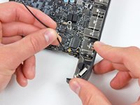
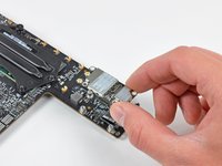
Simultaneously push the two plastic clips on the far left and right sides of the I/O board toward the middle of the I/O board and pull the I/O board away from the outer case.
-
-
crwdns2935267:0crwdne2935267:0Tweezers$4.99
-
Pull the I/O board/logic board assembly out of the outer case enough to access the power connector.
-
Use a pair of tweezers to disconnect the power cable from the logic board.
-
-
-
Carefully slide the logic board assembly out of the mini, minding any cables that may get caught.
-
-
-
Remove the following two screws securing the speaker to the logic board assembly:
-
One 4.2 mm T6 Torx
-
One 3.7 mm T6 Torx
-
-
-
Carefully lift the speaker wires upward to lift the speaker connector up and out of its socket on the logic board.
-
-
-
Use the flat end of a spudger to pry the antenna connectors up off the AirPort/Bluetooth board.
-
-
-
De-route both antenna cables from the clips securing them to the top side of the logic board.
-
-
-
Remove the single 2.6 mm T6 Torx screw securing the I/O bezel to the logic board near the RAM.
-
-
-
Carefully un-clip the antenna from the logic board near the PRAM battery.
-
Gently de-route the antenna cable through the hole in the logic board.
-
De-route the antenna cable from the clips on the logic board near the I/O bezel.
-
-
-
Lift the power button cables upward to gently pull the power button cable up and out of its connector on the logic board.
-
-
-
Remove the four 2.6 mm T6 Torx screws securing the I/O bezel to the logic board.
-
-
-
Pull the I/O bezel away from the logic board, minding any cables that may get caught.
-
-
-
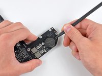
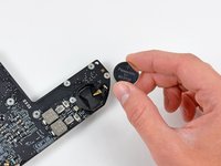
Use the tip of a spudger to carefully pry the PRAM battery up and out of its holder on the logic board.
-
Remove the PRAM battery and set it aside.
-
-
-
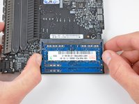
Release the tabs on each side of the RAM chip by simultaneously pushing each tab away from the RAM.
-
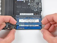
After the RAM chip has popped up, pull it straight out of its socket.
-
-
-
Use the flat end of a spudger to pry the AirPort/Bluetooth ribbon cable connector up off the AirPort/Bluetooth board.
-
-
-
Remove the three 2.6 mm T6 Torx screws securing the AirPort/Bluetooth board to the logic board.
-
Remove the AirPort/Bluetooth board and set it aside.
-
-
-
Use the flat end of a spudger to pry the AirPort/Bluetooth ribbon cable up off the logic board.
-
Remove the AirPort/Bluetooth ribbon cable.
-
-
-
Remove the single 5 mm T6 Torx standoff from the heat sink.
-
-
-
To disconnect the heat sink thermal sensor, pinch its cables between your thumb and a spudger and pry the spudger upward to lift the connector up and out of its socket on the logic board.
-
-
-
Remove the four 8.5 mm T8 Torx screws securing the heat sink to the logic board.
-
-
-
Carefully lift the heat sink off the logic board, minding the thermal sensor cable that may get caught.
-
If you need to mount the heat sink back onto the logic board, we have a thermal paste guide that makes replacing the thermal compound easy.
-


To reassemble your device, follow these instructions in reverse order.
crwdns2935221:0crwdne2935221:0
crwdns2935229:020crwdne2935229:0

crwdns2947412:07crwdne2947412:0
I'm confused, in step 11 the antenna plate is removed from the case, then in step 12 the bare logic board is out. What happened to the rest of the removal process?
barmour04 - crwdns2934203:0crwdne2934203:0 crwdns2950251:0crwdne2950251:0
Hey sorry about that, the guide was missing a prerequisite. I went through and made sure all the guides are OK. It should be fixed now. Good catch!
Andrew Bookholt - crwdns2934203:0crwdne2934203:0 crwdns2950251:0crwdne2950251:0
Does the logicboard of the Mac mini 2011 or 2012 fit in the Mac mini 2010?
Kristian - crwdns2934203:0crwdne2934203:0 crwdns2950251:0crwdne2950251:0
I’d really like to know this as well if anyone knows
Daniel W Olson - crwdns2934203:0crwdne2934203:0 crwdns2950251:0crwdne2950251:0
I'd like to know also
Collin Babb - crwdns2934203:0crwdne2934203:0 crwdns2950251:0crwdne2950251:0