crwdns2915892:0crwdne2915892:0
Use this guide to replace a faulty power supply.
crwdns2942213:0crwdne2942213:0
-
-
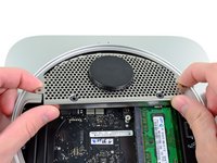
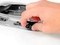
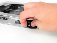
Place your thumbs in the depressions cut into the bottom cover.
-
Rotate the bottom cover counter-clockwise until the white dot painted on the bottom cover is aligned with the ring inscribed on the outer case.
-
-
-
Tilt the mini enough to allow the bottom cover to fall away from the outer case.
-
Remove the bottom cover and set it aside.
-
-
-
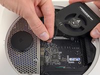
Remove the two 11.3 mm T6 Torx screws securing the fan to the logic board near the antenna plate.
-
-
-
Lift the ear of the fan nearest the RAM up off the standoff secured to the outer case.
-
-
-
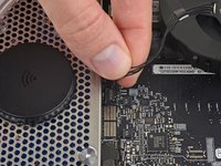
Lift the fan out of the mini for enough clearance to access its connector.
-
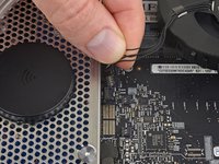
Grab all the wires at once and gently pull straight up to disconnect the fan from the logic board.
-
Remove the fan.
-
-
-
Remove the single 3.5 mm T6 Torx screw securing the cowling to the heat sink.
-
-
-
Lift the cowling from the end nearest the antenna plate.
-
Rotate the cowling away from the outer case and remove it from the mini.
-
-
-
Remove the following screws securing the antenna plate to the mini:
-
Two 6.6 mm T8 Torx screws
-
Two 5.0 mm T8 Torx or 2.0 mm Hex screws (either screwdriver will work)
-
When putting back together:
-
-
-
-
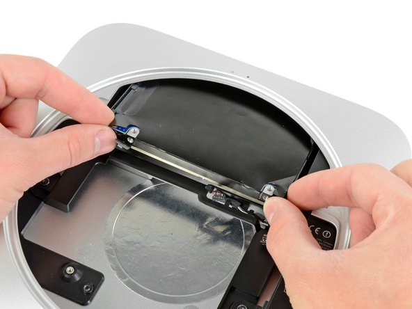
Slightly lift the antenna plate from the end closest to the RAM.
-
Carefully pull the antenna plate away from the circular rim of the outer case.
-
-
-
Use the tip of a spudger to carefully pry the antenna connector up from its socket on the AirPort/Bluetooth board.
-
-
-
Remove the antenna plate from the mini.
-
-
-
Use the flat end of a spudger to pry the hard drive connector up from its socket on the logic board.
-
-
-
Use the tip of a spudger to lift the IR sensor connector up and out of its socket on the logic board.
-
-
-
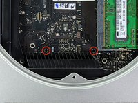
Remove the following three screws:
-
One 5.0 mm T8 Torx or 2.0 mm Hex screw (either screwdriver will work)
-
One 16.2 mm T6 Torx screw
-
One 26 mm T6 Torx standoff
-
-
crwdns2935267:0crwdne2935267:0Mac mini Logic Board Removal Tool$4.99
-
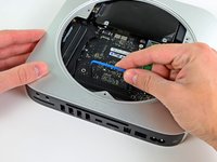
Insert the Mac mini Logic Board Removal Tool into the two holes highlighted in red. Be sure it makes contact with the top side of outer case below the logic board before proceeding.
-
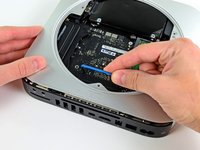
Carefully pull the tool toward the I/O board. The logic board and I/O board assembly should slightly slide out of the outer case.
-
Remove the Mac mini Logic Board Removal tool.
-
-
-
Pull the I/O board/logic board assembly out of the outer case enough to access the power connector.
-
Use your fingers to disconnect the DC-In cable from the logic board.
-
Pull the power cable connector toward the front side of the mini.
-
-
-
Carefully slide the logic board assembly out of the mini, minding any cables that may get caught.
-
-
-
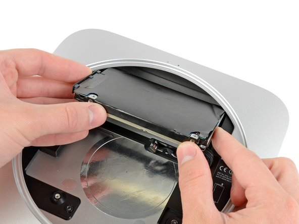
Pull the hard drive away from the front edge of the mini and remove it from the outer case.
-
-
-
Remove the 7.9 mm T6 Torx screw securing the power supply and hard drive tray to the outer case.
-
-
-
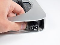
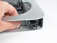
Pull the silver metal AC-In socket retainer away from the side of the outer case and remove it from the mini.
-
-
-
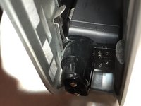
Rotate the AC-In connector 90 degrees counter-clockwise.
-
-
-
Slide the power supply out of the mini, minding any cables that may get caught.
-


To reassemble your device, follow these instructions in reverse order.
crwdns2935221:0crwdne2935221:0
crwdns2935229:043crwdne2935229:0


crwdns2947412:010crwdne2947412:0
Hello,
Can you please mention the part number of the powersupply module.
Shakthi Gs - crwdns2934203:0crwdne2934203:0 crwdns2950251:0crwdne2950251:0
The instructions mention a T6, and T8 screwdrivers. The “Buy these tools” link to T6 and T8 security screwdrivers. There is no mention of the security version of these screwdrivers required. Can someone clarify?
akobelan - crwdns2934203:0crwdne2934203:0 crwdns2950251:0crwdne2950251:0
For the late 2012 Apple Mac Mini, You do not need the security version of either the T6 nor the T8. However, I use the iFixit Pro Tech Tool Kit so mine are security torx. Either will work in this case. Goodluck!
(I’ve taken apart plenty of Apple products as well as 3 mac mini’s this week alone 2011, 2012, and 2012. They start using Safety Torx in 2014 to keep “clumsy customers” out. However that does not keep out the enthusiasts ;)
The best advice I can offer following this repair manual is to read all the steps carefully prior to disassembly / assembly. Go at it carefully and methodically. And refrain from caffeine a few days prior. It really sucks to drop a screw inside the case at step 18.
akobelan - crwdns2934203:0crwdne2934203:0 crwdns2950251:0crwdne2950251:0
can the power supply be tested IN PLACE with volt amp meter? i can see the power supply pins after Step 3. many people i see searching for this want to know if their power supply is good or if failure is also the logic board. i would stop disassembly if logic board has failed. also would know if one had to order power supply and logic board immediately/at the same time. Thank you!
dArKeR - crwdns2934203:0crwdne2934203:0 crwdns2950251:0crwdne2950251:0