crwdns2915892:0crwdne2915892:0
Completely replacing the logic board requires removal of the logic board itself as well as all components attached to it. Reinstallation will require reapplication of thermal compound to the CPU.
crwdns2942213:0crwdne2942213:0
-
-
Place your thumbs in the depressions cut into the bottom cover.
-
Rotate the bottom cover counter-clockwise until the white dot painted on the bottom cover is aligned with the ring inscribed on the outer case.
-
-
-
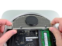
Tilt the mini enough to allow the bottom cover to fall away from the outer case.
-
Remove the bottom cover and set it aside.
-
-
-
Remove the two 11.3 mm T6 Torx screws securing the fan to the logic board near the antenna plate.
-
-
-
Lift the ear of the fan nearest the RAM up off the standoff secured to the outer case.
-
-
-
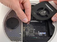
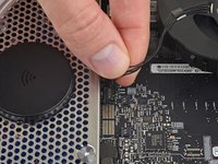
Lift the fan out of the mini for enough clearance to access its connector.
-
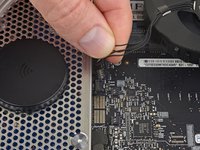
Grab all the wires at once and gently pull straight up to disconnect the fan from the logic board.
-
Remove the fan.
-
-
-
Remove the single 3.5 mm T6 Torx screw securing the cowling to the heat sink.
-
-
-
Lift the cowling from the end nearest the antenna plate.
-
Rotate the cowling away from the outer case and remove it from the mini.
-
-
-
Remove the following screws securing the antenna plate to the mini:
-
Two 6.6 mm T8 Torx screws
-
Two 5.0 mm T8 Torx or 2.0 mm Hex screws (either screwdriver will work)
-
When putting back together:
-
-
-
Slightly lift the antenna plate from the end closest to the RAM.
-
Carefully pull the antenna plate away from the circular rim of the outer case.
-
-
-
Use the tip of a spudger to carefully pry the antenna connector up from its socket on the AirPort/Bluetooth board.
-
-
-
-
Remove the antenna plate from the mini.
-
-
-
Use the flat end of a spudger to pry the hard drive connector up from its socket on the logic board.
-
-
-
Use the tip of a spudger to lift the IR sensor connector up and out of its socket on the logic board.
-
-
-
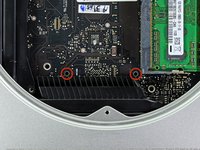
Remove the following three screws:
-
One 5.0 mm T8 Torx or 2.0 mm Hex screw (either screwdriver will work)
-
One 16.2 mm T6 Torx screw
-
One 26 mm T6 Torx standoff
-
-
crwdns2935267:0crwdne2935267:0Mac mini Logic Board Removal Tool$4.99
-
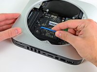
Insert the Mac mini Logic Board Removal Tool into the two holes highlighted in red. Be sure it makes contact with the top side of outer case below the logic board before proceeding.
-
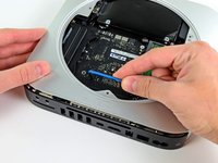
Carefully pull the tool toward the I/O board. The logic board and I/O board assembly should slightly slide out of the outer case.
-
Remove the Mac mini Logic Board Removal tool.
-
-
-
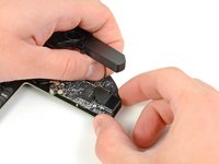
Pull the I/O board/logic board assembly out of the outer case enough to access the power connector.
-
Use your fingers to disconnect the DC-In cable from the logic board.
-
Pull the power cable connector toward the front side of the mini.
-
-
-
Carefully slide the logic board assembly out of the mini, minding any cables that may get caught.
-
-
-
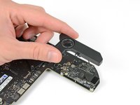
Use the tip of a spudger to carefully pry the PRAM battery up and out of its holder on the logic board.
-
-
-
Remove the PRAM battery from the logic board.
-
-
-
Remove the following two screws securing the speaker to the logic board assembly:
-
One 3.5 mm T6 Torx screw
-
One 3.7 mm T6 Torx screw
-
-
-
Carefully lift the speaker wires upward to lift the speaker connector up and out of its socket on the logic board.
-
Lift and remove the speaker away from the logic board.
-
-
-
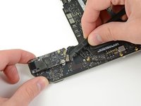
Use the flat end of a spudger to pry both antenna connectors up from their sockets on the AirPort/Bluetooth board.
-
-
-
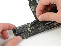
Use your spudger to help disconnect the AirPort/Bluetooth ribbon cable from its socket on the AirPort/Bluetooth board.
-
-
-
Remove the two 2.6 mm T6 Torx screws securing the AirPort/Bluetooth board to the logic board.
-
-
-
Remove the AirPort/Bluetooth board from the logic board.
-
-
-
Use the flat end of a spudger to pry the AirPort/Bluetooth ribbon cable up off the logic board.
-
Remove the AirPort/Bluetooth ribbon cable.
-
-
-
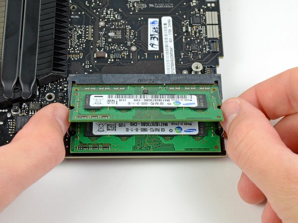
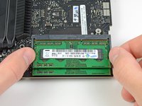
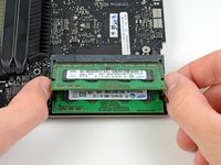
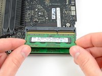
Release the tabs on each side of the RAM chip by simultaneously pushing each tab away from the chip.
-
After the RAM chip has popped up, pull it straight out of its socket.
-
-
-
Remove the single 5 mm T6 Torx standoff from the heat sink near the edge of the logic board.
-
-
-
Remove the following screws securing the heat sink to the logic board:
-
Four 8.6 mm T8 Torx screws
-
One 2.6 mm T6 Torx screw
-
-
-
Remove the heat sink from the logic board, minding any cables that may get caught.
-
Logic board remains.
-


To reassemble your device, follow these instructions in reverse order. Be sure to follow our thermal paste guide to reapply the thermal compound on the CPU.
crwdns2935221:0crwdne2935221:0
crwdns2935229:021crwdne2935229:0

crwdns2947412:04crwdne2947412:0
I ran a hardware test on my MacMini 2012 an it gave me the error 4SNS/1/C0000008: TAOP--124. I cannot use the Mac mini anymore because the fan is on full speed and kernel_task is on >300%.
I already know that the error is the Ambient Temperature sensor but i haven't got any hint where it is located. Similar threads on forums are always about MacBooks.
Do you know wether this sensor is on the logic board or is it external? What sensors does the Mac mini 2012 has?
Many thanks.
Just a heads up, after step #15, before #16, fishing out the hard drive makes pulling the DC-In cable to the Logic Board exponentially easier.
Step 17 shows the logic board being removed with the port cover intact. Step 30 shows the logic board without the port cover. There’s no mention in between of how that cover comes off. Anyone?
Deroute the wifi cables. You will see a connector to the board on its underside for the wifi: pry up from underneath the cable to free the connector from the board. Then there's 5 T6 screws to remove, 4 on the underside, one on the top. Now there's a small insulator glued to the board between the card reader and USB ports. Pull that off. You'll need to glue that back upon reassembly. Next, you gently wiggle the board away from the port cover. I would do this upside down from the orientation of the last picture, as there are 3 foam insulators that will fall out if you do it the other way. They are not connected at all, so be prepared for them to move around as soon as the board is loose. Reverse to put it back together.