crwdns2915892:0crwdne2915892:0
The IO board hosts all of the ports on your Mac Pro: Thunderbolt, USB, 3.5 mm speaker and headphone jacks, Ethernet ports, and HDMI. Use this guide to replace the IO board.
Before beginning any work on your Mac Pro: Unplug the computer and press and hold the power button for ten seconds to discharge the power supply's capacitors.
Be very careful not to touch the capacitor leads or any exposed solder joints on the back of the power supply. Only handle the board by the edges.
crwdns2942213:0crwdne2942213:0
-
-
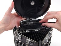
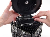
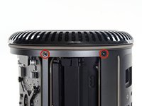
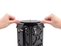
Slide the lock switch to the right, to the unlocked position.
-
-
-
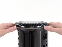
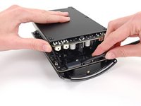
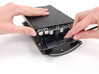
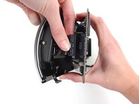
Lift the outer case straight up off the Mac Pro.
-
-
-
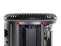
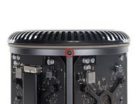
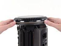
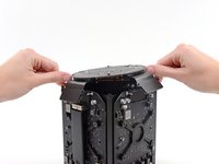
Remove five 5.1 mm T10 Torx screws from around the outer perimeter of the fan assembly.
You don't have to remove the fan assy to get to the wifi board & card. It can be done with the fan assy still attached.
Fat Mango is correct. That said. If you do pull the fan assembly note that the screws are all held in with blue Permatex and breaking them free takes a fair amount of effort. Getting a good set of Torx screwdrivers is a must.
Hey guys, what would happen if you only replace one card.. I have a D300 but the plan is to upgrade to D500 or D600. So If I can afford and install one instead of the pair would it increase something? or will it cause any conflict? I guess I don’t understand if I the Mac Pro has 2 D300 graphic cards that means each has 1GB? Same as If I would Install 1 D600 that would increase 3GB only? Thanks.
D300 = 2GB each card. Very few apps uses two cards at the same time.
Gio Cas -
The (5) Screws are Apple part number 923-0713
-
-
-
Tilt the assembly up away from the IO board.
-
-
-
While supporting the fan assembly with one hand, loosen the two T8 captive screws in the fan cable bracket.
On my Mac Pro (assembled mid-2017) these are T8 screws. In fact, there were no T7 screws anywhere in my machine.
There was no bracket on top of the cable at all, so I got a bit confused, so I had to skip step 5 and 6.
On my machine, a TR7 worked to remove them due to the weird angle.
-
-
crwdns2935267:0crwdne2935267:0Tweezers$4.99
-
Use a pair of tweezers to pull the fan cable bracket away from the fan assembly.
-
-
-
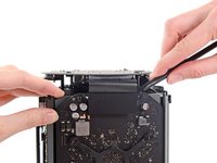
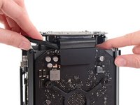
Use the flat end of a spudger to disconnect the fan assembly ribbon cable from the IO board.
-
-
-
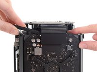
Disconnect the fan assembly antenna cable from the IO board.
-
Remove the fan assembly from the Mac Pro.
You don't have to remove the fan assy to do the steps below. They can be done with the fan assy still attached.
-
-
-
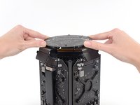
Remove five 5.1 mm T10 Torx screws from the outer perimeter of the lower case.
-
-
-
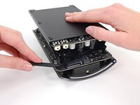
Carefully lift the lower case up and remove it from the Mac Pro.
-
-
-
-
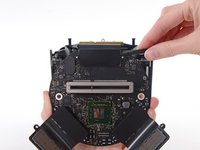
Use the flat end of a spudger and a twisting motion to gently separate one side of the graphics card data connection.
-
-
-
Gently separate the other side as well.
-
Flip the connector up and out of the way of the graphics card.
-
-
-
Remove the two 6.0 mm T8 Torx screws securing the interconnect board to the heat sink.
These are actually 6.0mm T8 Torx Screws. 12/07/2016.
Ended up being T9 screws for me.
On my Mac Pro (assembled mid-2017) these are T8 screws. In fact, there were no T7 screws anywhere in my machine.
These are T8 screws in my 2013 Mac Pro.
T8 screws for me, i did and edit to this step
Ended up being T15 screws on my machine
-
-
-
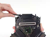
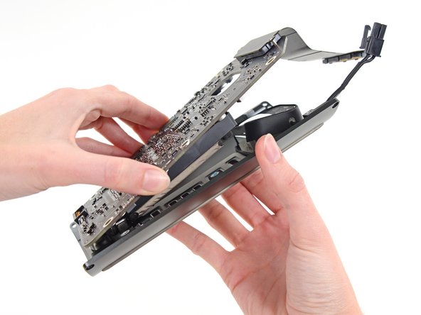
Gently walk the interconnect board straight up off the logic board's slot connection.
-
-
-
Flip the interconnect board up and over, exposing the IO board data cable.
-
Use the same sort of twisting and spreading motion with the flat end of a spudger to separate one side of the IO board data cable.
-
-
-
Use the flat end of a spudger to separate the other side of the IO board data cable.
-
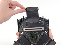
Bend the cable out of the way and remove the interconnect board from the Mac Pro.
-
-
-
Flip the Mac Pro back over and set it gently on a flat surface.
-
-
-
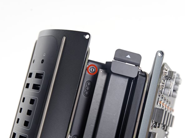
Remove the two 3.6 mm T5 Torx screws from the sides of the power supply cage (one on each side).
those are t4 screws in my mac
T4s on mine, as well
-
-
-
Remove the power supply cage from the top of the power supply.
-
-
-
Remove the four 5.5 mm T8 Torx screws securing the power supply assembly to the Mac Pro.
-
-
-
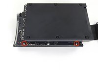
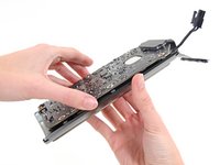
Remove the power supply assembly from the Mac Pro.
-
-
-
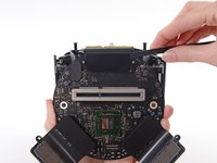
Use the flat end of a spudger to disconnect the power supply DC-Out connector from its socket on the IO board.
-
Use the tip of a spudger to disconnect the power supply data cable from its socket on the IO board.
Need to add T9 Torx Screwdriver to list of tools at the beginning of this article.
When I gently pried up on the power supply data cable, the entire socket came right off the board. Now what?
Bought a new I/O board and got it back together. This little socket is held in only by 4 tiny solder joints. Suggest pressing down on the socket with a finger while gently prying up on the plug that snaps into it. (When reassembling, it presses in vertically.)
-
-
-
Remove the four 9.0 mm silver T10 Torx screws from the sides of the power supply.
I managed to untie the screws at an angle using the T9 screwdriver (instead of the T10) works well.
awesome. thank you for the tip!!
A T-10 tip used with a 4mm or 5/32” open-end wrench to loosen helps, too. (These really should be hex bolts…)
-
-
-
Gently shift the power supply to free the AC power inlet cable out of its plastic clip.
-
-
-
Flip the power supply back to expose the AC power inlet cable.
-
-
-
Squeeze the AC power inlet cable connector and pull it straight out of its socket in the power supply.
-
-
-
Remove the two 9 mm silver T10 Torx screws securing the IO Board to the IO shield.
On reassembly, before tightening these 2 9.0mm T10s, make sure the other 4 holes line up. Otherwise you might be setting yourself up for cross threading the 4 remaining 9.0 mm T10 that are already in a bad spot for torquing.
Might not be a bad idea to put the other 4 halfway in to be sure no resistance, then tighten the 2 in this step, then remove the other 4.
-
-
-
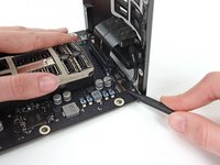
Lift the IO board up from the IO shield from the end with the AC plug.
-
-
-
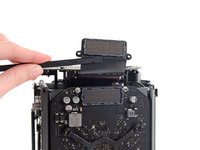
Use the tip of a spudger to flip the retaining flap on the IO shield ribbon cable ZIF connector.
-
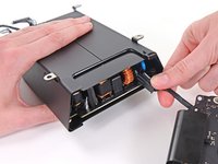
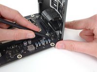
Disconnect the IO shield ribbon cable.
This step is unnecessary as you can access the battery already.
-
-
-
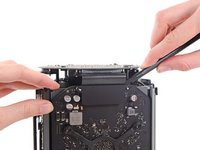
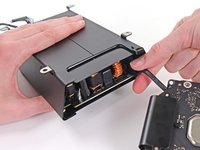
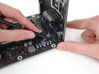
Squeeze and pull the audio jack ribbon cable connector from the IO board.
This step is unnecessary as you can access the battery already.
-


To reassemble your device, follow these instructions in reverse order.
To reassemble your device, follow these instructions in reverse order.
crwdns2935221:0crwdne2935221:0
crwdns2935229:05crwdne2935229:0

crwdns2947412:03crwdne2947412:0
How do you even get the a t10 to fit a such an aggressive angle?
My USB ports don’t work.. I replaced this board and they still don’t work.. Suggestions as to what could be causing this?
I’m having a severe problem with the data cable the runs from the power supply to the IO board. First, I broke a couple of the pins, so I had to order a new IO board. Now the pins are slightly different. Before, they were just sitting out unprotected, but the new board I purchased has a type of barrier around it, but my data cable won’t fit onto the pins now with the new protective barriers. Please help!