crwdns2915892:0crwdne2915892:0
The Mac Pro features two 3.5 mm audio jacks: a combined optical digital audio output and analog line out minijack. Use this guide to replace these components.
Before beginning any work on your Mac Pro: Unplug the computer and press and hold the power button for ten seconds to discharge the power supply's capacitors.
Be very careful not to touch the capacitor leads or any exposed solder joints on the back of the power supply. Only handle the board by the edges.
crwdns2942213:0crwdne2942213:0
-
-
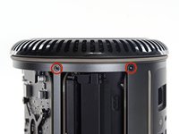
Slide the lock switch to the right, to the unlocked position.
-
-
-
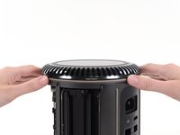
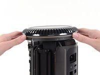
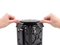
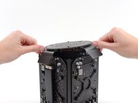
Lift the outer case straight up off the Mac Pro.
-
-
-
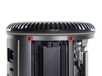
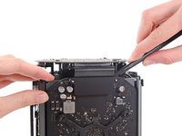
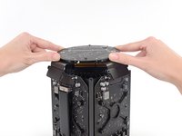
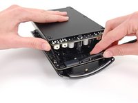
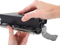
Remove five 5.1 mm T10 Torx screws from around the outer perimeter of the fan assembly.
-
-
-
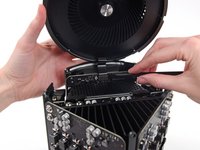
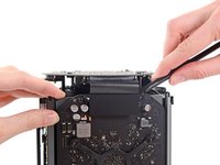
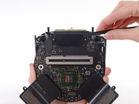
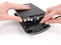
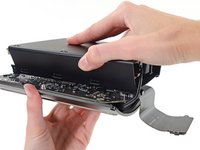
Tilt the assembly up away from the IO board.
-
-
-
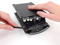
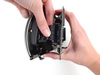
While supporting the fan assembly with one hand, loosen the two T8 captive screws in the fan cable bracket.
-
-
crwdns2935267:0crwdne2935267:0Tweezers$4.99
-
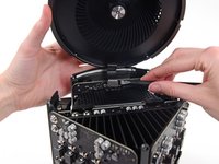
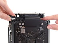
Use a pair of tweezers to pull the fan cable bracket away from the fan assembly.
-
-
-
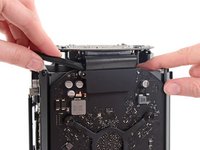
Use the flat end of a spudger to disconnect the fan assembly ribbon cable from the IO board.
-
-
-
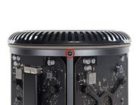
Disconnect the fan assembly antenna cable from the IO board.
-
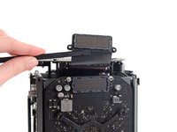
Remove the fan assembly from the Mac Pro.
-
-
-
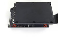
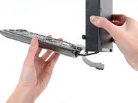
Remove five 5.1 mm T10 Torx screws from the outer perimeter of the lower case.
-
-
-
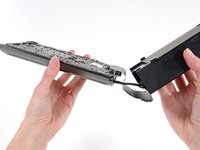
Carefully lift the lower case up and remove it from the Mac Pro.
-
-
-
Use the flat end of a spudger and a twisting motion to gently separate one side of the graphics card data connection.
-
-
-
-
Gently separate the other side as well.
-
Flip the connector up and out of the way of the graphics card.
-
-
-
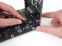
Remove the two 6.0 mm T8 Torx screws securing the interconnect board to the heat sink.
-
-
-
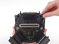
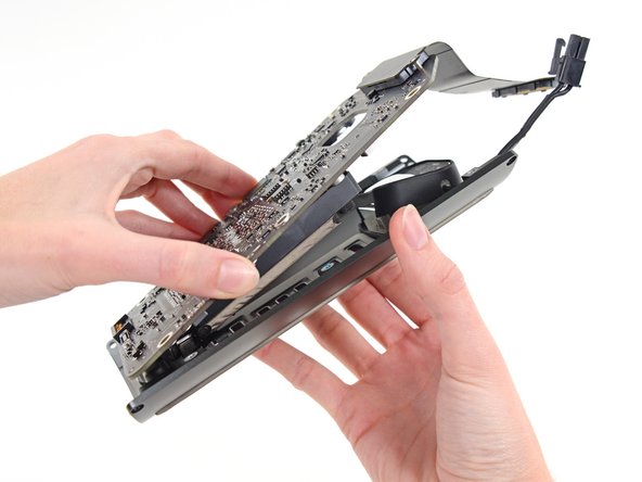
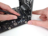
Gently walk the interconnect board straight up off the logic board's slot connection.
-
-
-
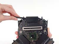
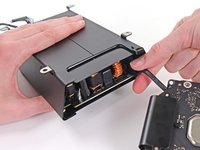
Flip the interconnect board up and over, exposing the IO board data cable.
-
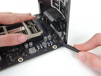
Use the same sort of twisting and spreading motion with the flat end of a spudger to separate one side of the IO board data cable.
-
-
-
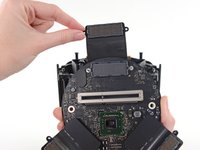
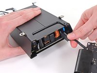
Use the flat end of a spudger to separate the other side of the IO board data cable.
-
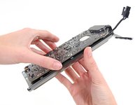
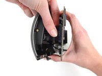
Bend the cable out of the way and remove the interconnect board from the Mac Pro.
-
-
-
Flip the Mac Pro back over and set it gently on a flat surface.
-
-
-
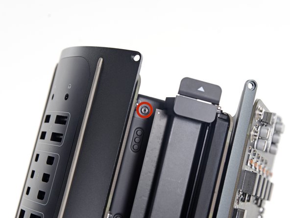
Remove the two 3.6 mm T5 Torx screws from the sides of the power supply cage (one on each side).
-
-
-
Remove the power supply cage from the top of the power supply.
-
-
-
Remove the four 5.5 mm T8 Torx screws securing the power supply assembly to the Mac Pro.
-
-
-
Remove the power supply assembly from the Mac Pro.
-
-
-
Use the flat end of a spudger to disconnect the power supply DC-Out connector from its socket on the IO board.
-
Use the tip of a spudger to disconnect the power supply data cable from its socket on the IO board.
-
-
-
Remove the four 9.0 mm silver T10 Torx screws from the sides of the power supply.
-
-
-
Gently shift the power supply to free the AC power inlet cable out of its plastic clip.
-
-
-
Flip the power supply back to expose the AC power inlet cable.
-
-
-
Squeeze the AC power inlet cable connector and pull it straight out of its socket in the power supply.
-
-
-
Remove the two 9 mm silver T10 Torx screws securing the IO Board to the IO shield.
-
-
-
Lift the IO board up from the IO shield from the end with the AC plug.
-
-
-
Use the tip of a spudger to flip the retaining flap on the IO shield ribbon cable ZIF connector.
-
Disconnect the IO shield ribbon cable.
-
-
-
Squeeze and pull the audio jack ribbon cable connector from the IO board.
-
-
-
Remove the three 3.7 mm T4 screws securing the audio jacks to the IO panel.
-
-
-
Carefully pull and remove the audio jacks straight away from the IO panel.
-


To reassemble your device, follow these instructions in reverse order.
To reassemble your device, follow these instructions in reverse order.
