crwdns2915892:0crwdne2915892:0
Use this guide to repair a power supply with frayed (crumbled insulation) AC-In Socket to Power Supply cable. Use this guide ONLY if you are not able to purchase a new Mac mini A1347 (Mid 2010) Power Supply.
Warning !
- Fixing the power supply requires working with conductors and a PCB that may carry high voltage from AC mains and charged PSU capacitors;
- If the AC wires are not properly insulated, they may short causing an electrical fire.
crwdns2942213:0crwdne2942213:0
-
-
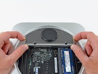
Place your thumbs in the depressions cut into the bottom cover.
-
Rotate the bottom cover counter-clockwise until the white dot painted on the bottom cover is aligned with the ring inscribed on the outer case.
-
-
-
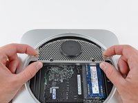
Tilt the mini enough to allow the bottom cover to fall away from the outer case.
-
Remove the bottom cover and set it aside.
-
-
-
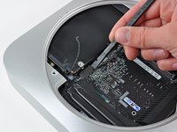
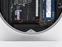
Remove the two 11.3 mm T6 Torx screws securing the fan to the logic board near the antenna plate.
-
-
-
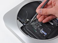
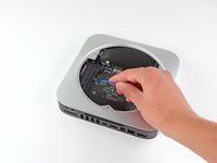
Lift the ear of the fan nearest the RAM up off the standoff secured to the outer case.
-
-
-
Lift the fan out of the mini for enough clearance to access its connector.
-
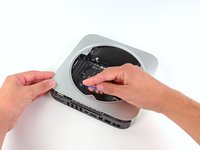
Carefully pull the fan cables upward to lift the fan connector up out of its socket on the logic board.
-
Remove the fan.
-
-
-
Remove the single 3.5 mm T6 Torx screw securing the cowling to the heat sink.
-
-
-
Lift the cowling from the end nearest the antenna plate.
-
Rotate the cowling away from the outer case and remove it from the mini.
-
-
-
Remove the following screws securing the antenna plate to the mini:
-
Two 6.6 mm T8 or T9 Torx screws
-
Two 5.0 mm T8 Torx or 2.0 mm Hex screws (either will work)
-
-
-
Slightly lift the antenna plate from the end closest to the RAM.
-
Carefully pull the antenna plate straight away from the circular rim of the outer case.
-
-
-
Use the tip of a spudger to carefully pry the antenna connector up off the AirPort/Bluetooth board.
-
-
-
-
Remove the antenna plate from the mini.
-
-
-
Remove the following three screws:
-
One 5.0 mm T8 Torx or 2.0 mm Hex screw (either will work)
-
One 16.2 mm T6 Torx screw
-
One 26 mm T6 Torx standoff
-
-
-
Carefully pull the wires for both hard drive thermal sensors upward to lift their connectors up and out of the sockets on the logic board.
-
-
-
Use the flat end of a spudger to pry both the hard drive and optical drive connectors up out of their sockets on the logic board.
-
-
-
To disconnect the optical drive thermal sensor, pinch its cables between your thumb and a spudger and pry the spudger upward to lift the connector up and out of its socket on the logic board.
-
-
-
Use the tip of a spudger to lift the IR sensor connector up and out of its socket on the logic board.
-
-
crwdns2935267:0crwdne2935267:0Mac mini Logic Board Removal Tool$4.99
-
Insert a Mac mini Logic Board Removal Tool into the two holes highlighted in red. Be sure it makes contact with the outer case below the logic board before proceeding.
-
Carefully pull the tool toward the I/O board. The logic board and I/O board assembly should slightly slide out of the outer case.
-
Cease prying when the I/O board is visibly separated from the outer case. Remove the Mac mini Logic Board Removal tool.
-
-
-
Simultaneously push the two plastic clips on the far left and right sides of the I/O board toward the middle of the I/O board and pull the I/O board away from the outer case.
-
-
crwdns2935267:0crwdne2935267:0Tweezers$4.99
-
Pull the I/O board/logic board assembly out of the outer case enough to access the power connector.
-
Use a pair of tweezers to disconnect the power cable from the logic board.
-
-
-
Carefully slide the logic board assembly out of the mini, minding any cables that may get caught.
-
-
-
Remove the 7.9 mm T6 Torx screw securing the power supply and optical drive to the outer case.
-
-
-
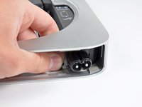
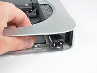
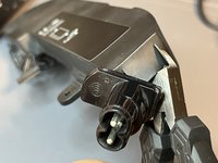
Pull the silver metal AC-In socket retainer away from the side of the outer case and remove it from the mini.
-
-
-
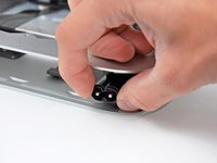
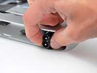
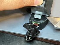
Rotate the AC-In connector 90 degrees counter-clockwise.
-
-
-
Slide the power supply out of the mini, minding any cables that may get caught.
-
-
-
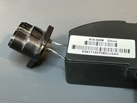
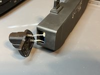
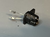
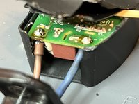
While opening a Mac Mini 2010 I discovered that the insulation on the short wires connecting the AC-In socket to the power supply was cracked. The "twist" operation to remove the AC-In socket from the case caused the wire insulation to crumble to small pieces. In the end, all the insulation fell off, the wires remained completely bare.
-
Mare sure the Power Supply is not connected to mains AC power while working on it.
-
Discharge the Power Supply before touching the wires by pushing the power button while the AC cable is unplugged then shorting the AC terminals in the plug with a screwdriver.
-
-
-
Follow the Mac mini Mid 2010 Power Supply Replacement guide to get to this point.
-
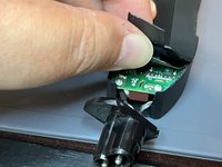
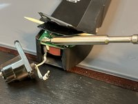
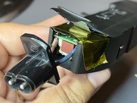
As the power supply case is made of glued thin plastic I used a flush cutter and a hobby knife to slice back the edges of the case about one inch, in order to get access to the PCB.
-
-
-
Peel up all the layers and prop them up (I used a toothpick). De-solder the two wire terminals - you will have to slightly pull down on the wire while melting the solder.
-
-
-
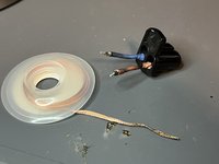
The AC wires actually have a crimped pin-plug on the end. You will have to use flux and soldering wick to clean as much solder from the so they fit back nicely in the original PCB holes.
-
After the solder blobs on the pins are removed, insert two pieces of heat-shrink tubing over the wires and hear them with a lighter/match/candle/hot air gun.
-
Also use soldering wick to clean the two holes in the PCB for easier reassembly.
-
-
-
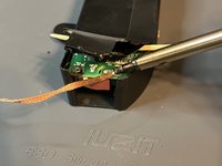
Solder the now-insulated wires back into their original PCB holes.
-
-
-
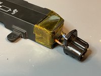
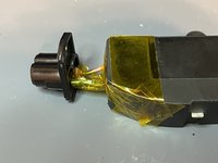
Use Kapton (Polyimide) high-temperature tape to re-close the PSU case. Depending on the tape, you might have to use your fingernail or a spudger to press on the tape so the adhesive makes good contact with the plastic case.
-


Now reassemble the Mac Mini and test it.

crwdns2935287:0crwdne2935287:0

Master Techs crwdns2935289:0Master Techscrwdne2935289:0
Community
crwdns2931471:0333crwdne2931471:0
crwdns2935297:01,477crwdne2935297:0