crwdns2915892:0crwdne2915892:0
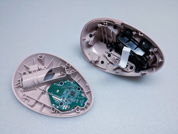
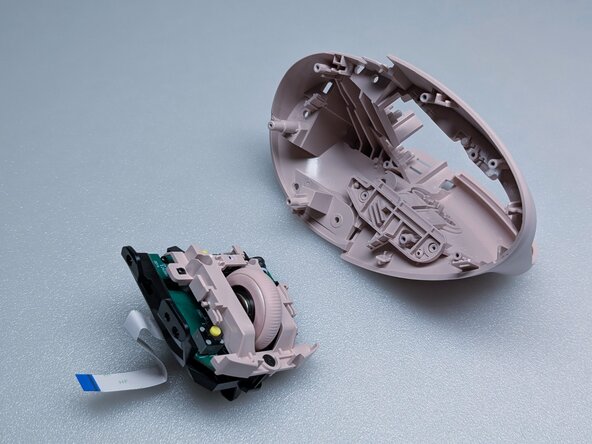
A complete disassembly of the Logitech Lift Vertical Ergonomic Mouse. This guide will show how to access to every part within the mouse.
crwdns2942213:0crwdne2942213:0
-
-
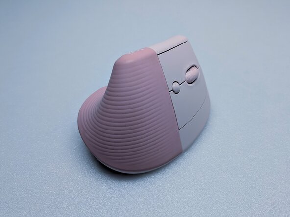
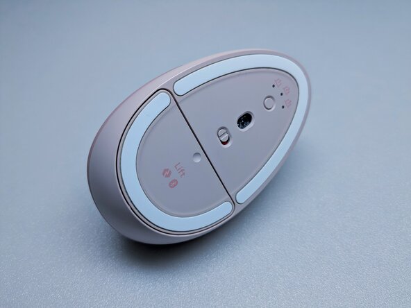
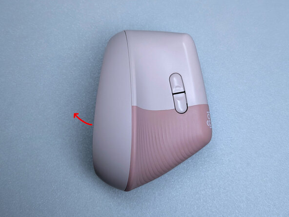
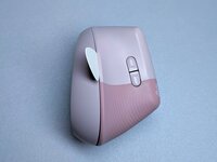
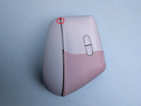
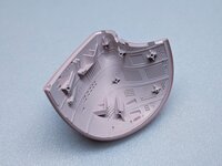
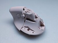
Exterior shots of the mouse. Flip over to begin.
-
-
-
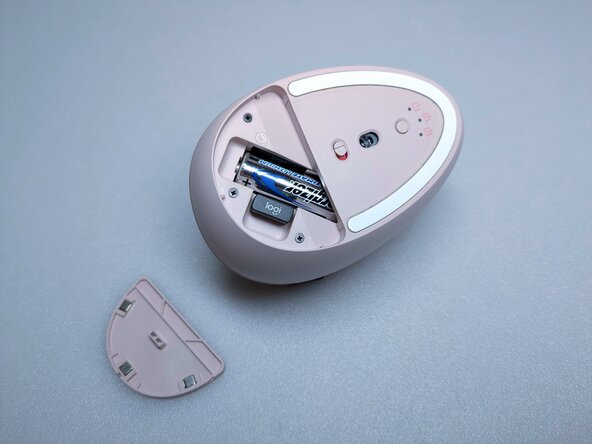
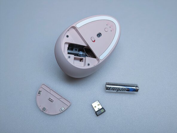
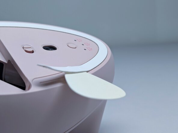
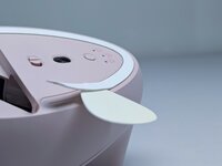
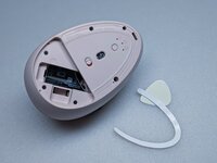
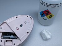
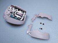
Remove the battery cover, battery, and USB receiver.
-
-
-
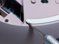
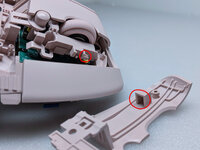
There are screws hidden beneath the PTFE skates. Carefully lift one end with a pointed tool and remove completely.
-
-
-
Use rubbing alcohol to clean the leftover adhesive, 91% isopropyl alcohol works well and does not damage the plastic. The PTFE skates will stick better during reassembly by doing this.
-
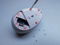
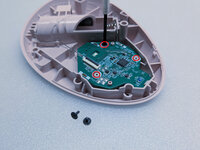
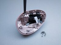
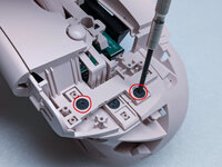
Remove the five screws highlighted in the photo. They are identical so mixing them is fine.
-
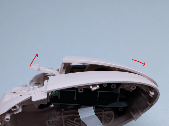
Gently pull the base apart from the top shell to expose a gap. The slot where the battery inserts into is a solid place to grip.
-
-
-
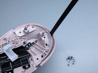
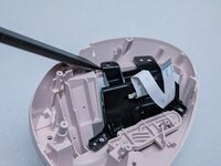
Use a guitar pick or similar plastic tool to further split the base from the top shell.
-
There is a clip that holds the two pieces together, highlighted in the second photo. Running the guitar pick across that area should pop it open.
-
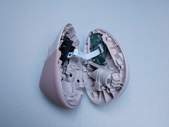
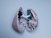
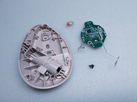
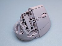
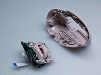
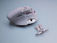
The base and top shell should separate with minimal force after the clip is undone.
-
-
-
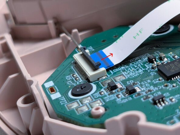
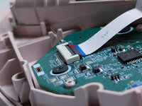
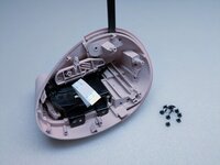
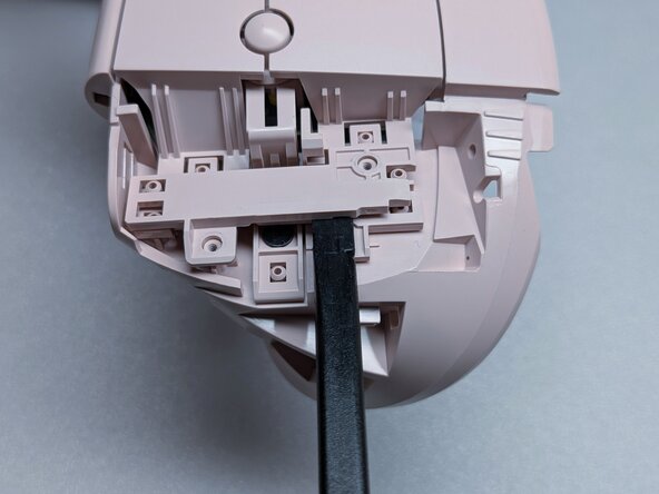
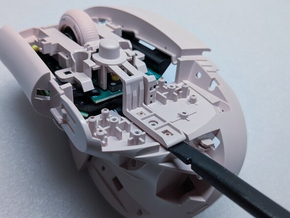
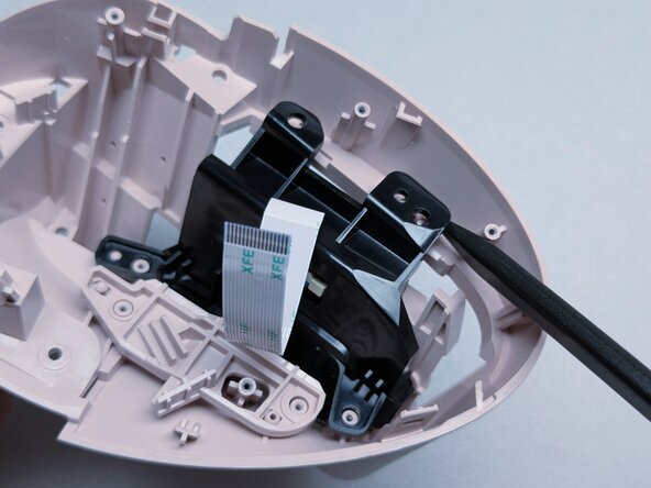
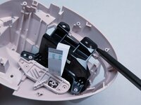
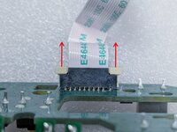
On the circuit board of the base, there is a connector holding the ribbon cable in place. Gently flip the black piece up with a fingernail and the cable can be removed with minimal force.
-
-
-
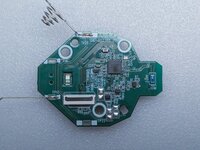
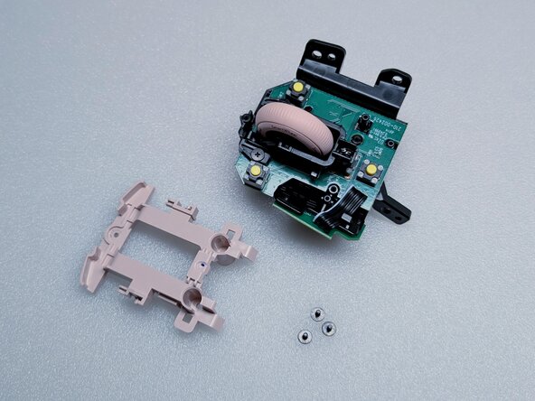
The sensor board is connected to the base with 3 identical screws. Remove them and the board can be lifted out easily by the battery contacts.
-
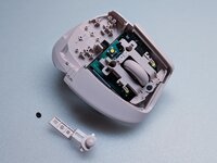
The power switch slider is loose and should drop out after the circuit board is removed. It can only be reassembled in one direction, so there's no need to keep track of the orientation.
-
-
-
-
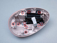
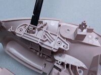
Remove all 11 screws that are visible in the top shell. They are identical so just keep them together in a safe place.
-
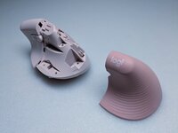
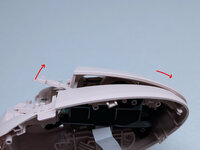
Gently pry at the rubber grip using a plastic tool like a spudger. This piece is held in strongly by a few plastic clips.
-
-
-
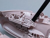
Continue prying around the grip, then pull the pieces apart.
-
-
-
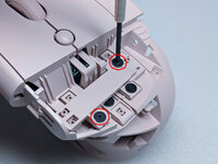
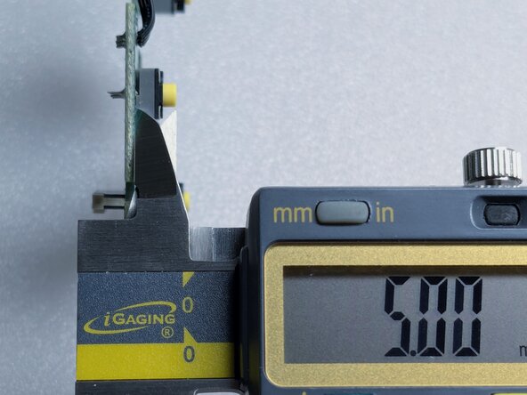
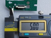
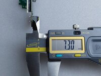
The right button is attached with two screws, as highlighted. These are different from screws from previous steps, so keep them separate.
-
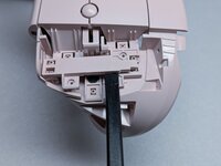
Gently lift the connecting piece with a tool, then continue lifting it while also pushing it forward, as seen in the third photo.
-
-
-
The button is held in place by a beam and its corresponding slot, which is why it cannot be lifted straight up.
-
Take out the 2 screws for the left button and remove it in the same way as the right button. The screws for these two buttons are the same.
-
-
-
Take out the screw holding the DPI button in place. It should come out easily with a bit of prying.
-
-
-
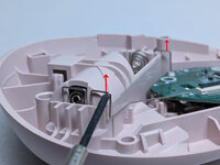
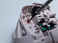
The switch assembly is snapped into place. Pry at the locations indicated in the first and second photo and it can be removed from the top shell with minimal force.
-
-
-
The side buttons are also held in with a snap fit. Pry at the locations indicated to loosen them. The buttons themselves might get caught on the casing, so push them in to remove them.
-
-
-
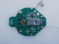
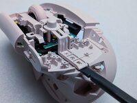
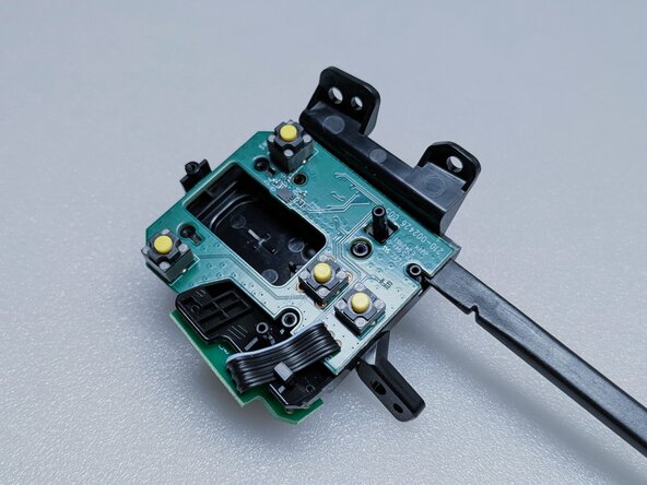
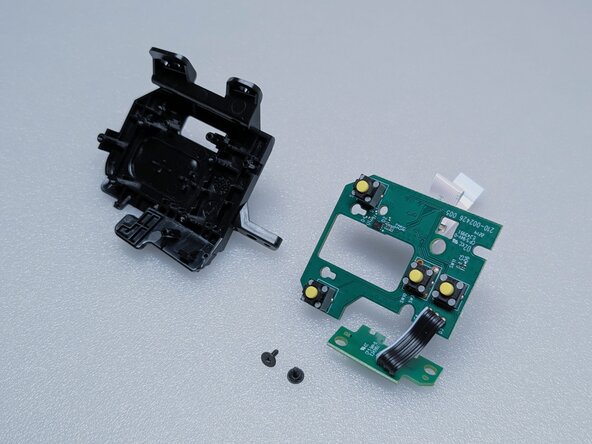
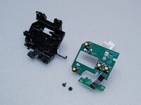
The switch button frame is held in place with 3 screws. Remove them and it will lift right out.
-
-
-
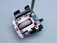
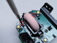
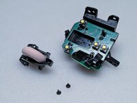
The scroll wheel is held in place with 2 screws.
-
-
-
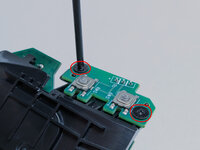
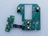
The side buttons are mounted to the frame with 2 screws. Once they are removed, the boards can be gently pried away from the frame.
-
-
-
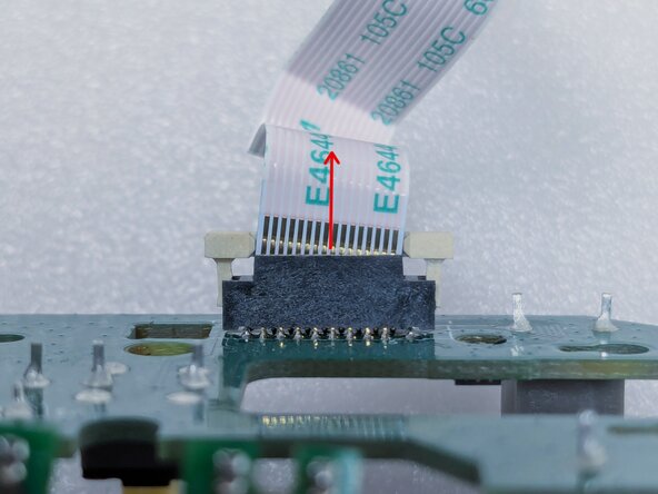
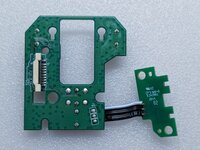
The ribbon cable can be released from the switch board by pulling on the two white tabs on the connector. The ribbon cable should come out very easily, do not force it.
-
-
-
Congrats! If you are reading this then either one of your primary buttons is probably double clicking. Best of luck with the repair!
-


crwdns2947412:02crwdne2947412:0
Thank You!!!
Thank you for this tear down. I was looking for ways to save this mouse I gave as a present as it was really ergonomic to use.
Whatever switches Logitech were soldering onto these are extremely unreliable.