crwdns2915892:0crwdne2915892:0
This guide will teach you to remove and replace the Logitech Harmony Smart Keyboard's Touchpad PCB.
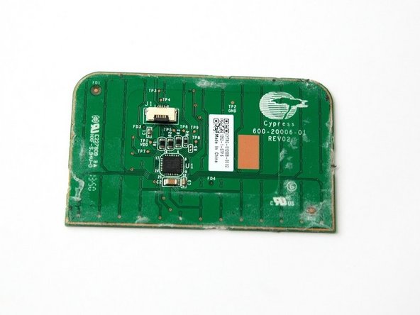
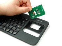
The printed circuit board (PCB) mechanically assists and electrically connects electronic parts using conductive tracks, pads and other components. The PCB appears in the form of a thin, copper board.
crwdns2942213:0crwdne2942213:0
-
-
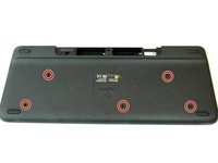
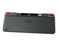
Turn keyboard over to the backside.
-
-
-
Press and slide up on the upper battery latch, using both thumbs.
-
-
-
Remove the two AA batteries and set them aside.
-
-
-
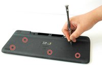
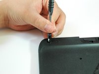
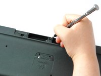
Unscrew all five 4.0 mm screws, using Phillips #1 screwdriver.
-
-
-
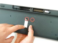
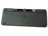
Peel off the center sticker to reveal two hidden 4.0 mm screws.
-
Unscrew these two screws with a Phillips #1 screwdriver.
-
-
-
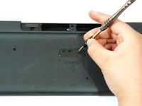
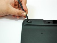
Lift both top left and top right rubber stickers halfway, using the sharp end of the plastic spudger.
-
Unscrew a total of two 4.0 mm screws, under the rubber stickers, using a Phillips #1 screwdriver.
-
-
-
-
Unscrew the top center 4.0 mm screw, in the battery compartment, using the Phillips #1 screwdriver.
-
-
-
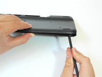
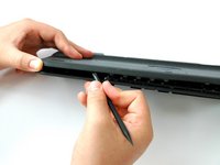
Wedge the flat end of the spudger between the back panel and front panel.
-
Slide the flat end of the spudger from right to left to pry the two panels apart.
-
-
-
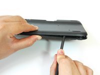
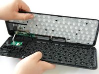
Separate the back panel from the front panel completely, using both hands.
-
-
-
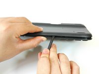
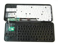
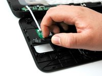
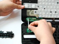
Lift up and pull off the track pad’s left and right clickers.
-
-
-
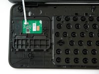
Grip the lower end of the ribbon flex cable (white band) using your thumb and index finger.
-
Then slide the strip out toward yourself in a scooping motion.
-
-
-
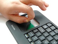
Flip the front panel over so the front side faces up, and rotate so the keys appear upside down.
-
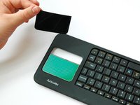
Lift the upper-right corner of the sensor sticker using the sharp end of the spudger and your index finger.
-
-
-
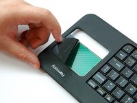
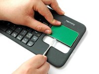
Peel the sticker off by pinching the sticker corner using your index finger and thumb.
-
-
-
Rotate the front panel around so the keys appear right-side up.
-
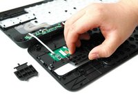
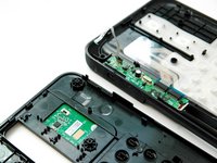
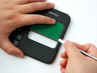
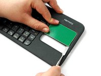
Wedge the flat-head metal spudger under the PCB's bottom-right corner.
-
Wedge and slide the spudger along the right side to reach the upper-right corner.
-
-
-
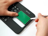
Wedge the flat-head metal spudger under the PCB's bottom-left corner.
-
Wedge and slide the spudger along the bottom side to reach the bottom-right corner.
-
-
-
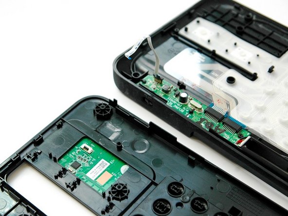
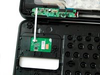
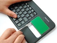
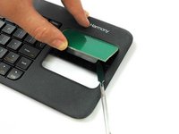
Slide and nudge the spudger upward underneath the PCB.
-
Wiggle and lift up the PCB with your thumb as you nudge the spudger up to release the PCB.
-


To reassemble your device, follow these instructions in reverse order.
To reassemble your device, follow these instructions in reverse order.
crwdns2915084:0crwdne2915084:0

CSU Fullerton, Team S1-G2, Bruce Fall 2017 crwdns2935289:0CSU Fullerton, Team S1-G2, Bruce Fall 2017crwdne2935289:0
CSUF-BRUCE-F17S1G2
crwdns2931471:03crwdne2931471:0
crwdns2935297:010crwdne2935297:0