crwdns2915892:0crwdne2915892:0
In this guide we will go over removing the top casing.
crwdns2942213:0crwdne2942213:0
-
-
Power down and unplug the device.
-
-
-
Remove the antennas from the back of the device. To do this, follow steps 1 and 2 of Installing the Antennas Guide: Linksys WAP54g Antennas Replacement
-
-
-
Remove the two black rubber feet of the device using the screwdriver. The feet are located on the bottom towards the front.
-
-
-
-
Once the feet are removed, two small screws will be visible. With a small screwdriver, unscrew them. Screws are phillips head, 4.35 mm in diameter, 7.88 mm in length.
-
-
-
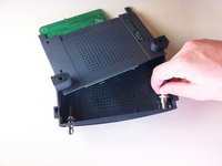
To remove the front blue panel, grip firmly and place thumbs in the two notches on top. Push thumbs forward while keeping a firm grip on bottom.
-
-
-
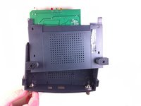
Now slide the bottom panel forward and remove it so the top casing is isolated from the bottom casing and motherboard.
-
-
-
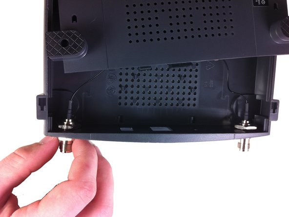
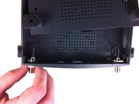
Unscrew the nut on the outer side of the back casing. Remove the nut and the washer from both antenna mounts.
-
-
-
From here, remove the wires and nuts connected to the back panel by pulling the nuts through the holes.
-
Now the top casing has been removed and isolated from the rest of the device. From here, you can make repairs to the top casing.
-


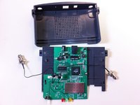
From here you can take apart the rest of the router apart by following subsequent guides.
From here you can take apart the rest of the router apart by following subsequent guides.
crwdns2935221:0crwdne2935221:0
crwdns2935227:0crwdne2935227:0
crwdns2915084:0crwdne2915084:0

Cal Poly, Team 21-21, Maness Fall 2011 crwdns2935289:0Cal Poly, Team 21-21, Maness Fall 2011crwdne2935289:0
CPSU-MANESS-F11S21G21
crwdns2931471:05crwdne2931471:0
crwdns2935297:012crwdne2935297:0
crwdns2947410:01crwdne2947410:0
Bon Tutoriel. Simple, mais les plastiques sont solidement attacher. Il faut donc forcer pour démonter la partie bleu. Mais c’est possible.
Merci.