crwdns2915892:0crwdne2915892:0
Before starting this guide, you should know how to solder. You can reference iFixit’s soldering guide here.
crwdns2942213:0crwdne2942213:0
-
-
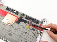
Remove the two Phillips #000 screws.
-
-
-
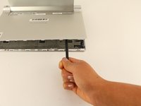
Use a plastic iFixit opening tool to pry the edges of the back case loose by placing it in between the edge of the cover and the screen.
-
-
-
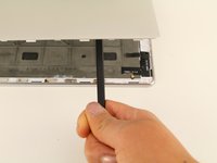
Use the spudger to reach into the center of the device and pry off the back case by giving it a light force upwards.
-
-
-
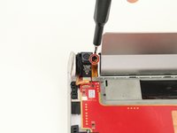
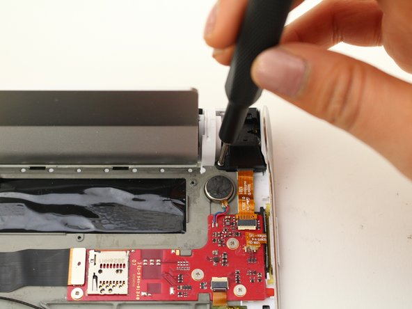
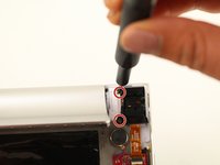
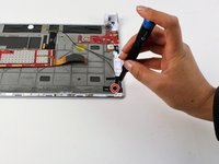
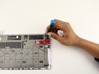
Remove one 5mm screw using the Phillips #00 Screwdriver.
-
-
-
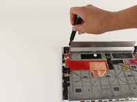
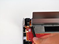
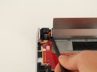
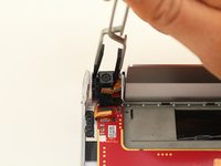
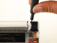
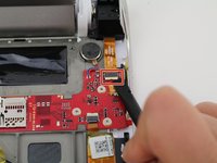
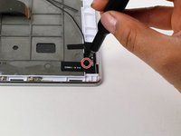
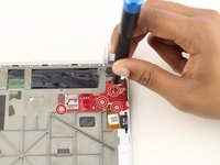
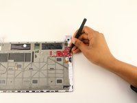
Use the spudger to disconnect the camera and battery from the printed circuit board by putting the spudger in between the connections and the printed circuit board and pushing the spudger up.
-
-
-
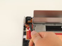
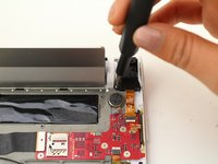
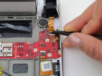
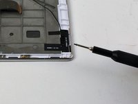
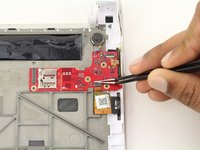
Remove one 5mm screw with the Phillips #00 screwdriver.
-
-
crwdns2935267:0crwdne2935267:0Tweezers$4.99
-
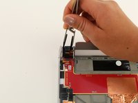
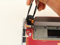
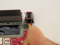
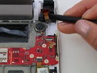
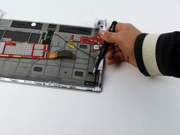
Use the nylon tip tweezers to push the camera out from between the power button and the kickstand.
-
-
crwdns2935267:0crwdne2935267:0Tweezers$4.99
-
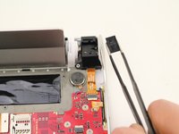
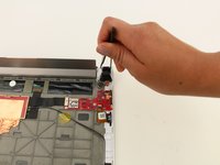
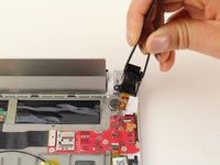
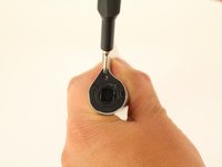
Remove the headphone jack cover with tweezers by grabbing it and pulling directly up and away from the device.
-
-
-
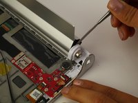
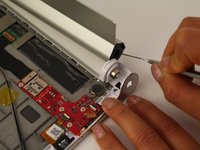
Remove the two 3.5mm screws using the Phillips #00 Screwdriver.
-
-
-
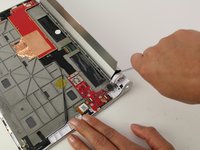
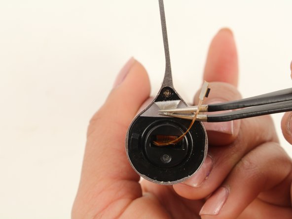
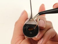
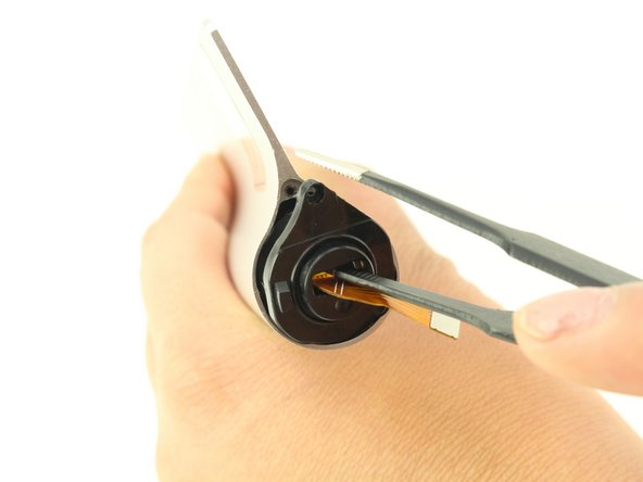
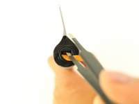
Disconnect the headphone jack from the motherboard by placing the spudger in between the connections and motherboard and pushing up towards you.
-
Pull the wire towards the headphone jack to disconnect it.
-
-
-
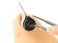
Use tweezers to remove the headphone jack by pulling it up and towards you.
-
-
-
-
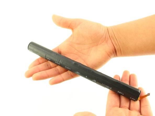
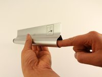
Use the metal spudger to push out the lock of the battery compartment by putting the metal spudger between the kickstand and the plastic and applying a force upwards.
-
-
-
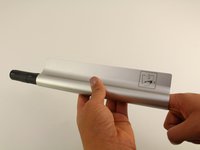
Pull the battery compartment away from the device.
-
-
crwdns2935267:0crwdne2935267:0Tweezers$4.99
-
Use tweezers to remove the gray tape and reveal a screw at each end of the compartment.
-
-
-
Remove one 3.5 mm screw from each end using the Phillips #00 screwdriver.
-
-
-
Use tweezers to remove the cap from the side with the orange connector coming out of it.
-
-
-
Use your hands to push the battery out towards the other side of the compartment.
-
-
-
Remove the four 1 mm screws with a Phillips #00 Screwdriver.
-
-
-
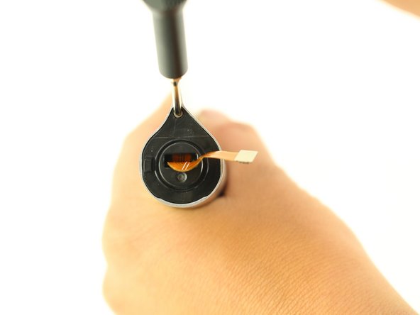
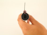
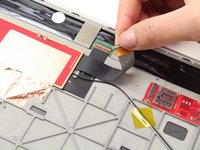
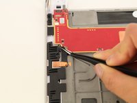
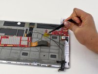
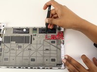
Use a spudger to disconnect the ribbon wire by applying a force upwards.
-
-
crwdns2935267:0crwdne2935267:0Tweezers$4.99
-
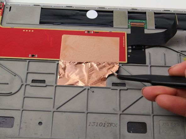
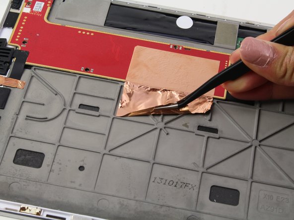
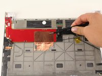
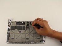
Use tweezers to lift up the foil.
-
-
-
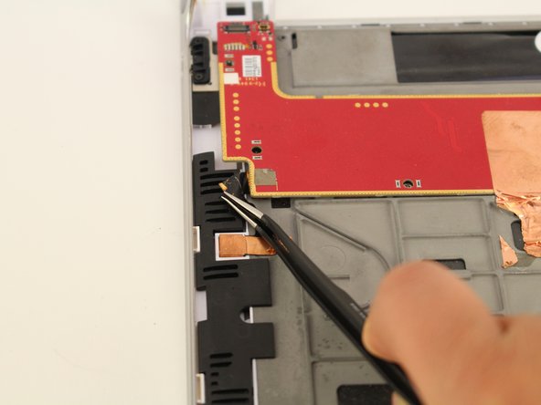
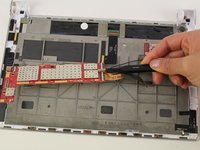
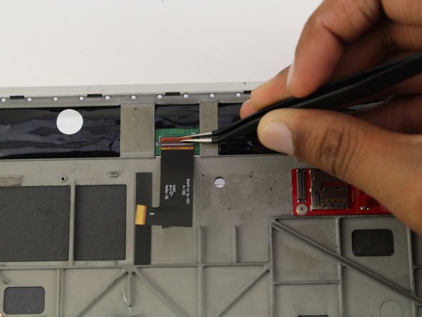
Use the tweezers to lift the black tape from the corner of the printed circuit board.
-
-
-
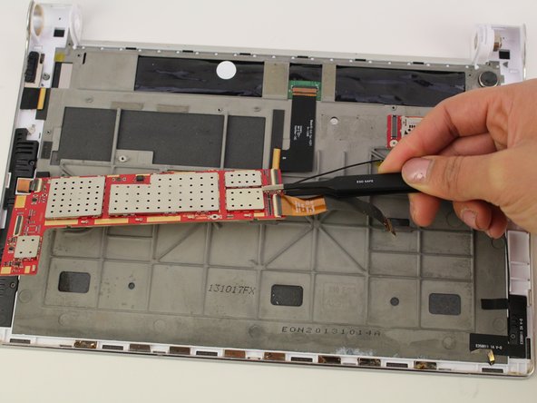
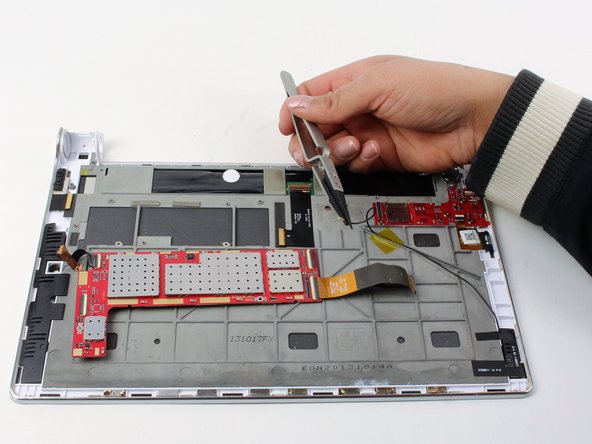
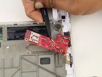
Flip the board 180 degrees towards you using the tweezers.
-
-
crwdns2935267:0crwdne2935267:0Tweezers$4.99
-
Remove the wire from the PCB by pulling it towards the edge of the headphone jack using tweezers.
-
-
-
Remove the one 5mm screw using a Phillips #00 Screwdriver.
-
-
-
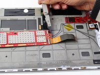
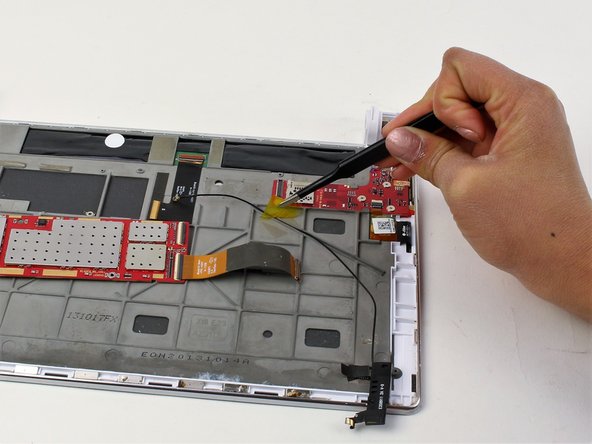
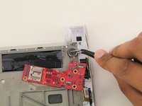
Using tweezers remove the tape to disconnect the module by pulling it upward.
-
-
-
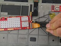
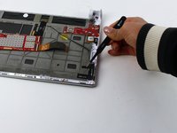
Remove the yellow piece of tape by pulling it upward using tweezers.
-
-
crwdns2935267:0crwdne2935267:0Tweezers$4.99
-
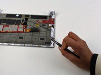
Peel off the ribbon wire using tweezers, and disconnect it from the motherboard.
-
-
-
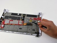
Remove the four 1mm Phillips #00 screws.
-
-
-
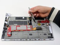
Disconnect the wire attached to the PCB by pulling it away using tweezers.
-
-
-
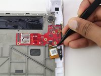
Desolder the wire.
-
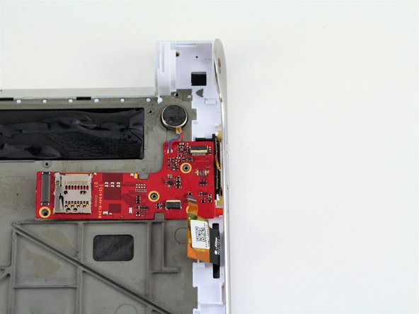
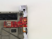
Remove the PCB and round vibration module.
-
-
-
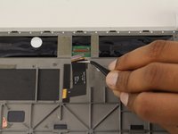
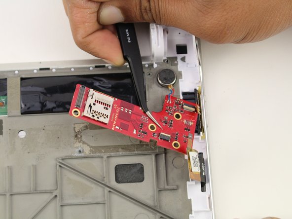
Use the precision tweezers to pry up the PCB along with the round vibration module from its bottom corner lifting it upwards .
-


To reassemble your device, follow these instructions in reverse order.
To reassemble your device, follow these instructions in reverse order.
crwdns2915084:0crwdne2915084:0

Cal Poly, Team S2-G6, White Winter 2019 crwdns2935289:0Cal Poly, Team S2-G6, White Winter 2019crwdne2935289:0
CPSU-WHITE-W19S2G6
crwdns2931471:04crwdne2931471:0
crwdns2935297:07crwdne2935297:0