crwdns2915892:0crwdne2915892:0
This guide includes all the steps, tools, and parts necessary to disassemble the Lenovo Yoga C930-13IKB to access and replace the hinge assembly.
crwdns2942213:0crwdne2942213:0
-
-
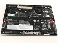
Flip the device over so that the underside is facing up.
-
Remove the six 3.5 mm T5 Torx screws.
-
-
-
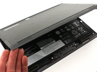
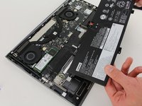
Pry off the back cover using the plastic opening tool.
-
Loosen the back cover in multiple spots using the opening tool, then remove the whole back.
-
-
-
Carefully lift the cover off with your hands.
-
-
-
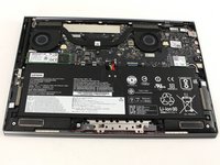
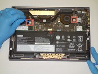
Unplug the battery from the motherboard by pinching the cables with your fingers and tugging out with force.
-
-
-
Unscrew the four 3mm screws with a Phillips screwdriver.
-
-
-
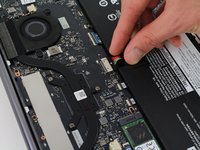
Use your fingers to pry up the clear plastic pull-tab for one of the stretch release adhesives.
-
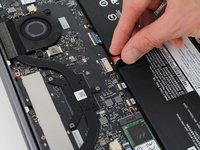
Grasp the pull-tab and slowly pull away from the battery at a shallow angle. The adhesive strip will stretch to many times its length and slowly release from underneath the battery.
-
Repeat the procedure for the second strip on the opposite side of the battery.
-
Remove the battery with your hands.
-
-
-
Remove the four 3 mm Phillips #0 screws from the fan assembly.
-
-
-
Remove the four 2 mm Phillips #00 screws from the fans themselves.
-
-
-
Unscrew the three 3 mm Phillips #0 screws on the heatsink.
-
-
-
Use a plastic opening tool to remove the two small, white power cable connectors for each of the two fans.
-
-
-
-
Gently lift the fan assembly out of the laptop.
-
-
crwdns2935267:0crwdne2935267:0Halberd Spudger$2.99
-
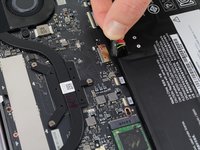
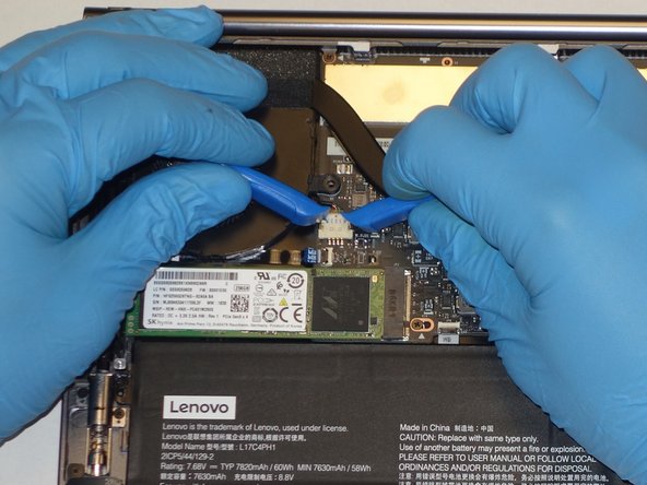
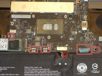
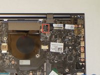
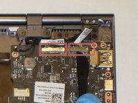
Using the Halberd Spudger, gently lift the black tab on top of each of the five ZIF connectors for the ribbon cables. Then pull the cables out from the connectors.
-
-
crwdns2935267:0crwdne2935267:0Tweezers$4.99
-
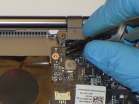
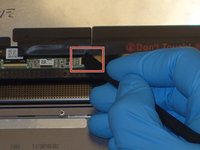
Using the reverse tweezers, gently pull out the small black cable towards the top right of the motherboard.
-
-
-
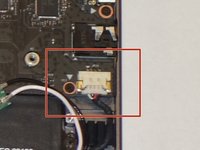
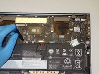
Using two plastic opening tools gently unplug the white speaker cable connector from the bottom left of the motherboard.
-
-
-
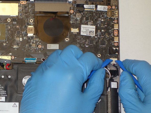
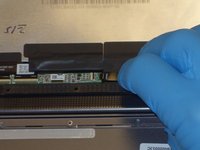
Using the plastic opening tool, gently pry up on the metal tabs of the two display cables to remove the cables from the top right corner of the motherboard.
-
-
-
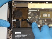
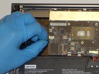
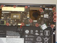
Remove the fourteen 3 mm Phillips #00 screws that hold in the motherboard.
-
-
-
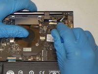
While gently grasping each side of the motherboard, carefully lift the assembly out.
-
-
crwdns2935267:0crwdne2935267:0Halberd Spudger$2.99
-
Using a halberd spudger, gently lift up the metal bezel that lines the lower edge of the display.
-
-
-
Remove the ten 3 mm screws along the bottom edge of the display with a Phillips #00 screwdriver.
-
-
crwdns2935267:0crwdne2935267:0iFixit Opening Picks (Set of 6)$4.99
-
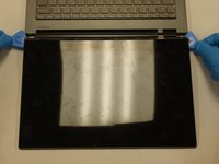
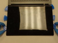
Gently wedge two opening picks underneath the display.
-
Slowly work the opening picks around the display.
-
Add opening picks as needed to keep display separated from the frame.
-
-
-
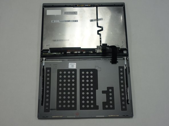
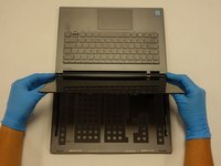
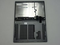
Gently flip the display assembly to rest on top of the keyboard.
-
-
-
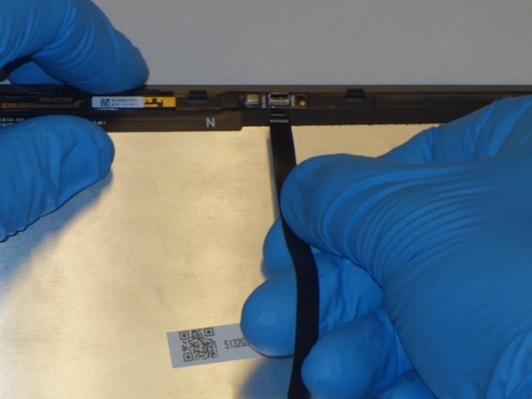
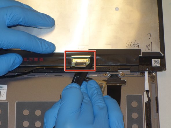
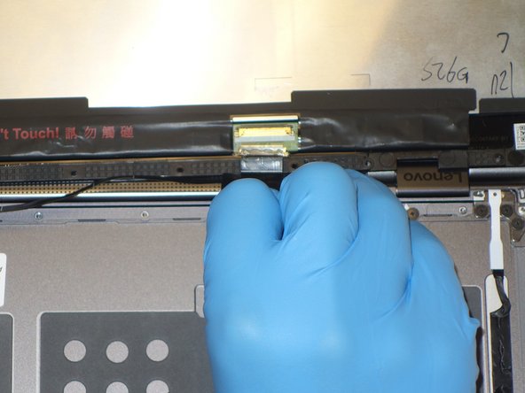
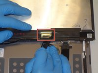
Use the halberd spudger to lift the locking tab of the ZIF connector holding the black ribbon cable that runs vertically across the display.
-
Pull out the black ribbon cable from the connector.
-
-
-
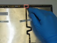
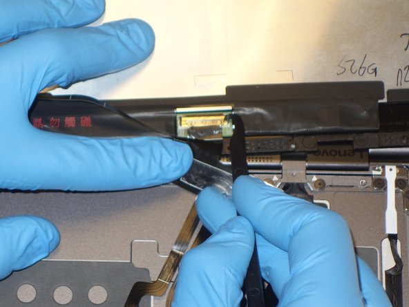
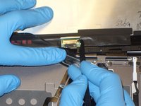
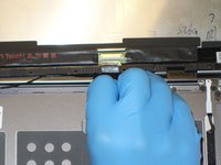
Use the halberd spudger to lift the latch on the ZIF connector of the horizontal black ribbon cable.
-
Pull out the horizontal black ribbon cable from the connector.
-
Gently pull the rest of the horizontal black ribbon cable from the back of the display.
-
-
-
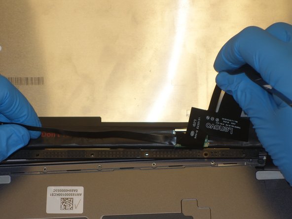
Use the halberd spudger to flip the metal latch of the display cable up.
-
Using the halberd spudger, gently pull the connector out of the display.
-
-
-
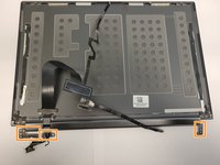
Gently lift the display away from the laptop frame.
-
-
-
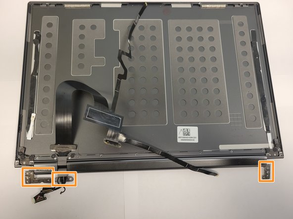
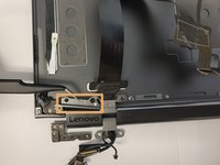
Remove the eight 3 mm screws from the hinge attachments on the back cover using the Phillips #00 screwdriver.
-
Carefully detach the hinge assembly connectors from the LCD cover to detach it from the back cover.
-
-
crwdns2935267:0crwdne2935267:0Tweezers$4.99
-
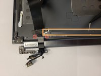
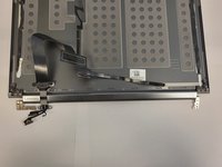
Using a Phillips #00 screwdriver, remove the two 3 mm screws from the hinge attachment on the LCD cover.
-
Detach the two hinge retention brackets using the angled ESD tweezers.
-
-
-
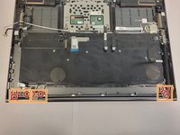
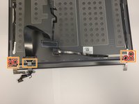
Using a Phillips #00 screwdriver remove the six 3 mm screws from the corners of the LCD cover.
-
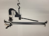
Carefully lift the hinge assembly, detaching it from the LCD cover.
-


To reassemble your device, follow these instructions in reverse order.
crwdns2935221:0crwdne2935221:0
crwdns2935229:04crwdne2935229:0

crwdns2935287:0crwdne2935287:0

The Citadel Military College of South Carolina, Team 2-14, Eggleston Fall 2021 crwdns2935289:0The Citadel Military College of South Carolina, Team 2-14, Eggleston Fall 2021crwdne2935289:0
CMCSC-EGGLESTON-F21S2G14
crwdns2931471:03crwdne2931471:0
crwdns2935297:03crwdne2935297:0
crwdns2947410:01crwdne2947410:0
Is it possible to just replace the hinge on the side that is broken, where the pin has snapped?