crwdns2915892:0crwdne2915892:0
This guide will demonstrate the process of replacing the motherboard in the Lenovo Yoga 900-13ISK. The motherboard handles computations for the laptop, and manages the inputs and outputs of all the other components. The motherboard is also home to the CPU and RAM, so any issues commonly associated to a failure with one of these components can be solved with a motherboard replacement. Common symptoms of a faulty motherboard in the Lenovo Yoga 900 are glitchy graphics, frequent crashes or freezes, the computer not turning on, and booting to an error screen. If you are experiencing any of these issues, and have ruled out a lesser component as the culprit, a motherboard replacement should help solve the problem.
The motherboard in the Lenovo Yoga 900 is connected to the heatsink and fan assembly, and these components will be removed from the computer as a single unit. If your replacement motherboard does not include the heatsink and fan assembly, you can transfer over your old cooling system using this heatsink guide.
Be sure to unplug and completely turn off your device before you start working.
crwdns2942213:0crwdne2942213:0
-
-
Using a T5 Torx screwdriver, remove the ten 5.5 mm screws from the back case of the laptop.
-
-
-
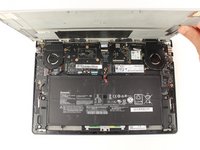
Use a spudger to pry open the back case at the hinges of the laptop.
-
Use your fingers to completely pop off the back cover.
-
-
-
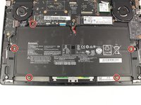
Remove the five 3.6 mm screws from the battery with a Phillips #00 screwdriver.
-
-
-
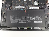
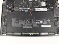
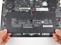
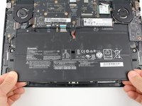
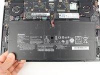
Grab the bottom corners of the battery and gently pull the battery until the cable disconnects from the connector on the motherboard.
-
-
-
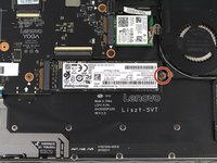
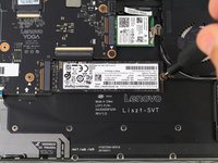
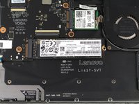
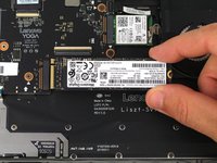
Use a Phillips #00 screwdriver to remove the 2.7 mm screw that is holding down the SSD card.
-
-
-
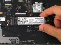
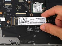
Pull the SSD card out of the port to the right.
-
-
-
-
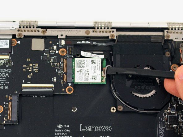
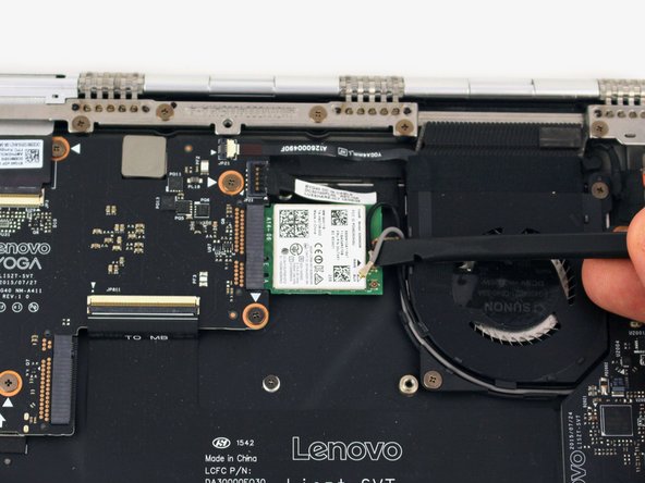
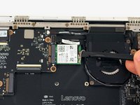
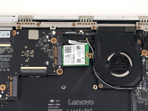
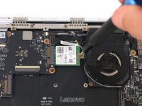
Pry up the gray and black coaxial cables from the Wi-Fi card using a spudger.
-
Move the cables to the side.
-
-
-
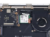
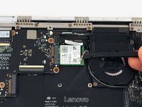
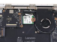
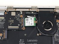
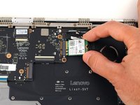
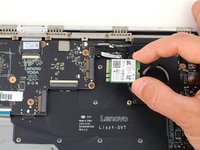
Using a Phillips #00 screwdriver, remove the 2.2 mm screw holding down the Wi-Fi card.
-
-
-
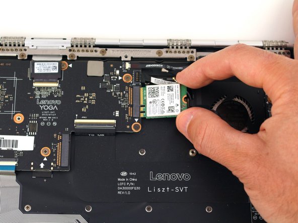
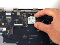
Pull the WiFi card out from the connector on the motherboard.
-
-
crwdns2935267:0crwdne2935267:0Tweezers$4.99
-
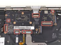
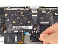
Using the pointed end of a spudger, flip up the hinged locking tabs of the eight ZIF connectors on the motherboard.
-
Pull the eight cables out from their connectors using a pair of blunt nose tweezers.
-
-
-
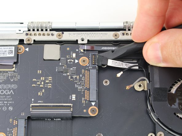
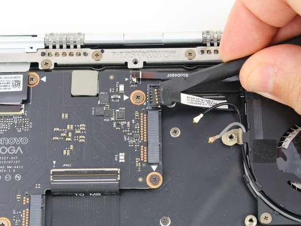
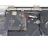
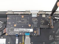
Use a spudger to pry up the press fit connector on the right side of the motherboard.
-
-
-
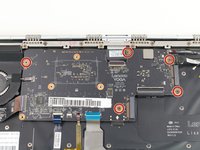
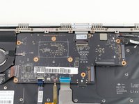
Remove the five 3.6 mm screws from the motherboard using a Phillips #00 screwdriver.
-
-
-
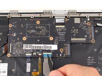
Pull back the interconnect cable on the left side of the motherboard to reveal one of the fan screws for the left fan.
-
Remove the two 3.6 mm screws from the left fan with a Phillips #00 screwdriver.
-
-
-
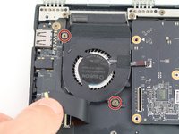
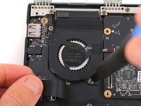
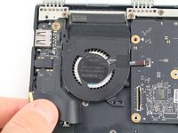
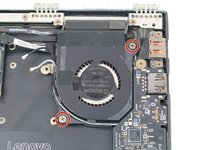
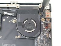
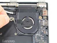
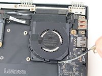
Remove the two 3.6 mm screws from the right fan using a Phillips #00 screwdriver.
-
-
-
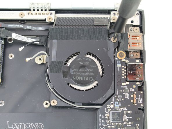
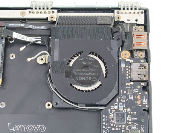
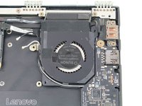
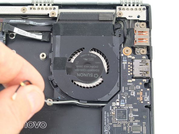
Unwind the black and white coaxial cables from the hooks on the right fan casing.
-
-
-
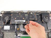
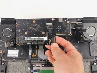
Lift the motherboard from the bottom edge and pull it up and out of the case.
-


To reassemble your device, follow these instructions in reverse order.
To reassemble your device, follow these instructions in reverse order.
crwdns2935221:0crwdne2935221:0
crwdns2935229:04crwdne2935229:0

