crwdns2915892:0crwdne2915892:0
Use this guide to replace the motherboard on a Lenovo Yoga 730 13-IKB (model numbers starting with “81CT”).
The motherboard is the printed circuit board that allows each component of your computer to communicate. These components include the Central Processing Unit (CPU), the Random Access Memory (RAM), and other hardware components.
A broken motherboard is difficult to diagnose because it connects to many different components. Major issues like failure to boot, blue screening, and burning odors are most likely indicators of motherboard problems. Review this guide to further diagnose a suspected bad motherboard.
Replacing the motherboard is an advanced process and is recommended for confident users. Keep any debris or liquids away from the computer while replacing the motherboard because the internal components of the laptop will be exposed.
crwdns2942213:0crwdne2942213:0
-
-
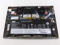
Remove the nine T5 screws fastening the back case.
-
-
-
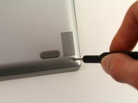
Slide a plastic opening tool underneath the back case near the screen hinges. Gently pry up on either side.
-
Slide the opening tool underneath the back case next to the middle screw hole at either side of the case. Gently pry up.
-
-
-
Remove the back case by pulling up near the screen hinges and lifting diagonally away from the laptop.
-
-
-
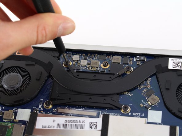
Use a Phillips #00 screwdriver to remove the eight 2.5mm screws securing the heat sink assembly.
-
-
-
Release the fan connector by gently pushing the gray locking tab up using a plastic spudger. Do this for both of the fans.
-
Pull each fan cable straight out of the connector.
-
-
-
Remove the heat sink assembly by holding the middle plate and rotating the assembly down towards the back of the motherboard.
-
Pull the heat sink diagonally away from the laptop.
-
-
-
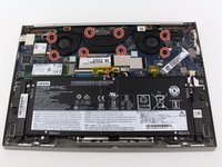
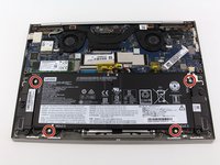
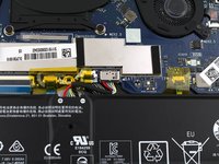
Remove the four 3.5mm Phillips #0 screws securing the battery.
-
-
-
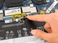
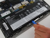
Disconnect the battery cable by gently pulling it straight out of the connector.
-
-
-
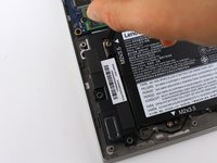
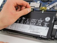
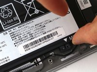
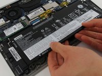
Remove the battery by pulling up near the white label and lifting diagonally away from the laptop.
-
-
-
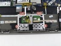
Use a Phillips #00 screwdriver to remove the six 2.5mm screws holding down the touch pad.
-
-
-
-
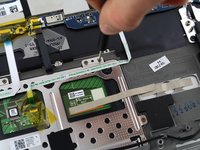
Peel back the fabric adhesive strap holding the speaker wire to the touchpad.
-
-
-
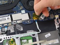
Peel off the fingerprint sensor cable glued to the top of the touchpad.
-
-
-
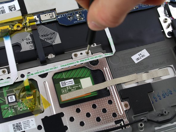
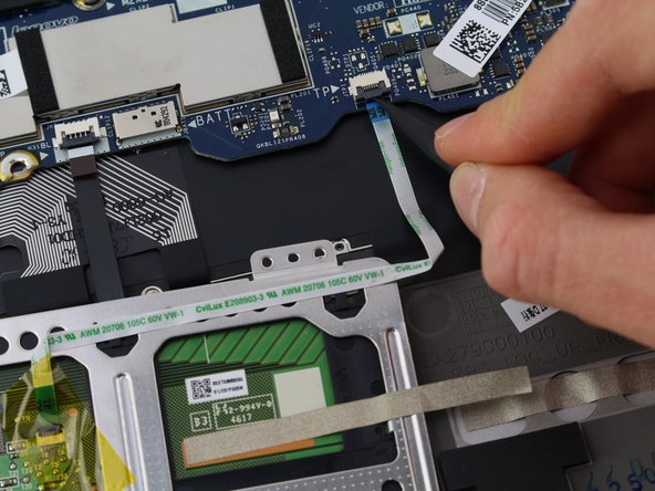
Slightly pull up the metal strap connecting the touchpad and the laptop frame.
-
-
-
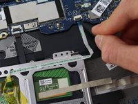
Peel the yellow tape off of the touchpad connector.
-
Gently push the gray tab up on the connector using a spudger. Pull out the cable.
-
-
-
Hold the top of the touchpad and gently pull up.
-
Lift the touchpad diagonally away from the laptop.
-
-
-
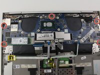
Use a Phillips #00 screwdriver to remove the five 3.5mm screws securing the motherboard.
-
-
-
Use a Phillips #000 driver to remove the four 3mm screws holding down the connector bracket.
-
-
-
Lift the bracket up from the motherboard and place aside.
-
-
-
Use a spudger to remove the bluetooth cable by flipping up the gray connector tab. Pull out the cable.
-
-
-
Use a spudger to remove the fingerprint sensor cable by flipping up the gray connector tab. Pull out the cable.
-
-
-
Use a spudger to remove the keyboard cable by flipping up the gray connector tab. Pull out the cable.
-
-
-
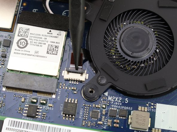
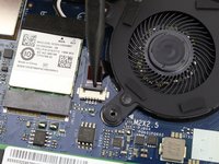
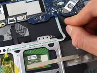
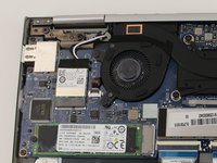
Peel the black adhesive strip covering the wires to the LAN card.
-
-
-
Use a Phillips #00 screwdriver to remove the 2.5mm screw securing the LAN card.
-
-
-
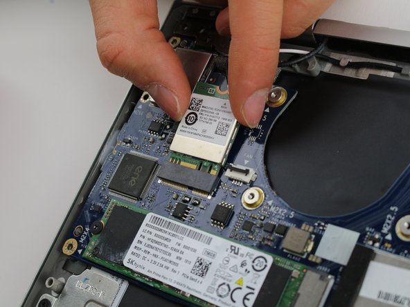
Gently slide the LAN card straight out of the motherboard connector.
-
-
-
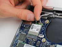
Disconnect the black and white wires from the LAN card.
-
-
-
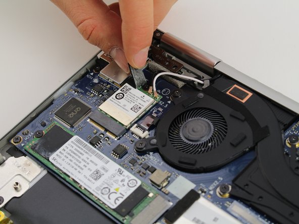
Peel back the adhesive cover connecting the display connector and hinge.
-
-
-
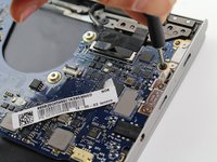
Lift the display connector straight up from the motherboard.
-
-
-
Remove the motherboard by holding it by the bottom and pulling diagonally away from the laptop.
-


To reassemble your device, follow these instructions in reverse order.
To reassemble your device, follow these instructions in reverse order.
crwdns2935221:0crwdne2935221:0
crwdns2935227:0crwdne2935227:0
crwdns2915084:0crwdne2915084:0

Cal Poly, Team S1-G1, White Winter 2020 crwdns2935289:0Cal Poly, Team S1-G1, White Winter 2020crwdne2935289:0
CPSU-WHITE-W20S1G1
crwdns2931471:03crwdne2931471:0
crwdns2935297:014crwdne2935297:0