crwdns2915892:0crwdne2915892:0
This guide details the steps to remove the motherboard from the Lenovo IdeaPad 110 Touch-15ACL laptop. The motherboard is essentially the heart of the computer and allows the computer to function. The motherboard is a thin-mostly rectangular component that has many wires attached to the other systems within the computer. These wires need to be removed before the motherboard can be removed. The screws which mount the motherboard to the case can be identified by a small white triangle ‘pointing’ to the screw. Exercise caution to mitigate damaging any other internal components and/or damaging the motherboard itself.
Before beginning this repair, be sure to turn off the laptop and disconnect from the power adapter.
crwdns2942213:0crwdne2942213:0
-
-
Remove the thirteen 6 mm Phillips #0 screws.
-
-
-
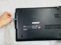
Use an opening tool to gently disconnect most of the clips on the back panel.
-
-
-
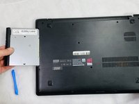
Pry the disk drive away from the center of the laptop.
-
Once the drive is removed, remove the one 2 mm Phillips #0 screw that is now exposed.
-
-
-
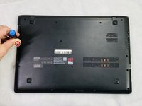
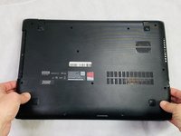
Unclip any of the remaining clips and remove the back panel.
-
-
-
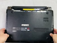
Remove the four 6 mm Phillips #0 mounting screws.
-
-
-
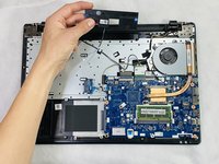
Detach the wire connected to the motherboard and remove the battery assembly.
-
-
-
-
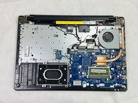
Remove the four 4 mm Phillips #0 mounting screws attaching the caddy to the frame.
-
-
-
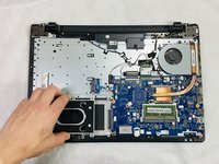
Gently remove the caddy away from the motherboard.
-
-
-
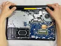
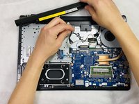
Detach the speaker wire from the motherboard.
-
-
-
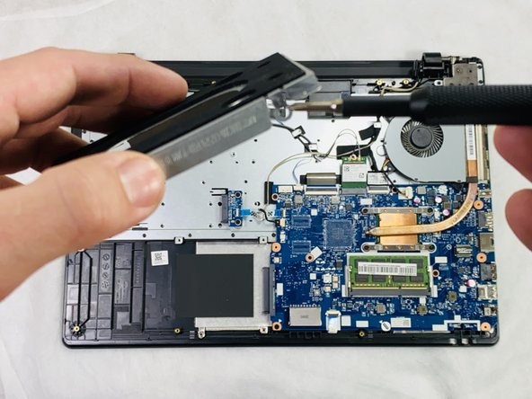
Gently pull upwards on the speaker assembly to remove it from the case.
-
-
-
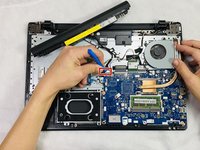
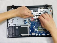
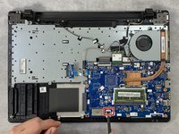
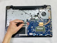
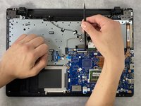
Unlock the ZIF connector and remove the wire connected at the bottom of the motherboard.
-
-
-
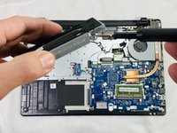
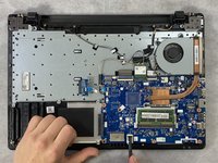
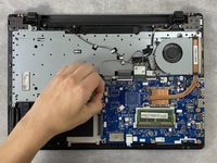
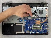
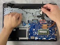
Disconnect the wires attached on the "left" side.
-
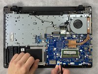
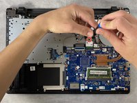
Use the spudger to unlock the clip to remove the blue ribbon cable.
-
-
-
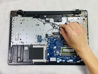
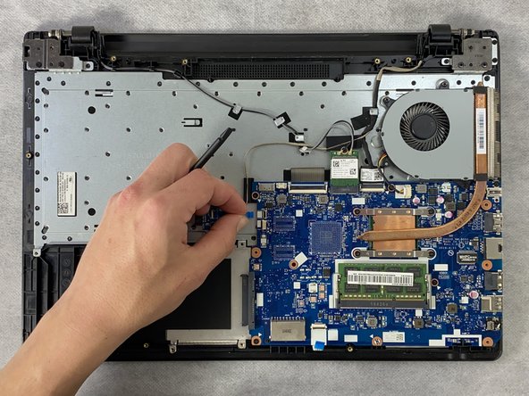
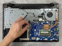
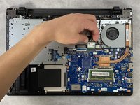
Unlock the ZIF connector at the top-left of the motherboard.
-
Remove the ribbon cable.
-
-
-
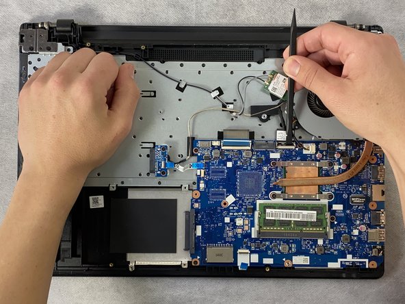
Remove the single 4 mm Philips #0 screw from the Wi-Fi card.
-
Slide the Wi-Fi card out of the socket.
-
-
-
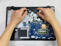
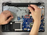
Unlock the remaining ZIF connector with a spudger.
-
Remove the ribbon cable.
-
-
-
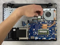
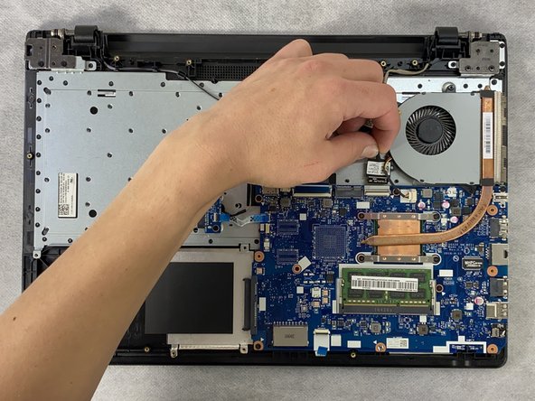
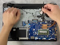
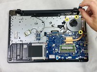
Disconnect the fan's wire from the motherboard.
-
Remove the four 3 mm Philips #0 screws joining the heatsink to the motherboard
-
Then, remove the three 5 mm Philips #0 screws holding the fan assembly to the frame.
-
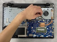
Remove the fan and heatsink.
-
-
-
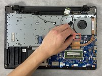
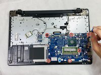
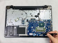
Once everything has been disconnected from the motherboard, remove the six 3 mm Philips #0 mounting screws from the motherboard.
-
-
-
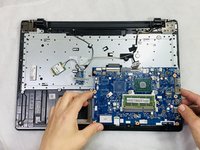
This is what the frame should look like once everything is removed.
-


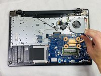


To reassemble your device, follow these instructions in reverse order.
To reassemble your device, follow these instructions in reverse order.
crwdns2915084:0crwdne2915084:0

Clemson, Team 2-3, Hunter Spring 2022 crwdns2935289:0Clemson, Team 2-3, Hunter Spring 2022crwdne2935289:0
CLEM-HUNTER-S22S2G3
crwdns2931471:05crwdne2931471:0
crwdns2935297:06crwdne2935297:0
crwdns2947410:01crwdne2947410:0
A general tip: when reassembling not all holes take in a screw even if they look that way. Some holes will get filled when you screw in the screws attaching the back panel, or if there are several layers of stuff attached the screw will go in on another level. But how to know where to put a screw in? Of course you can study the back panel or the other layers to see where the screws go and compare to the screw holes inside but there is an easier way. In almost all the circuit boards there will be a small triangle printed right next to a hole that takes a screw on that particular level. If there are several holes next to each other, examine the printed triangle. There is always one "corner" of the triangle pointing right at the hole where you are supposed to put a screw in. Some of you guys already know this, but as these guides are read by newcomers looking for easy instructions and tips I'm sure not all do. I figured this out by myself and it made my life a lot easier. No more screwing aroung in vain :D