crwdns2933423:0crwdne2933423:0

LG OLED TV - Power supply board troubleshooting and repair

crwdns2942213:0crwdne2942213:0

  1. LG OLED TV - Power supply board troubleshooting and repair, Netzteilplatine entfernen: crwdns2935265:01crwdnd2935265:01crwdnd2935265:02crwdne2935265:0 LG OLED TV - Power supply board troubleshooting and repair, Netzteilplatine entfernen: crwdns2935265:01crwdnd2935265:02crwdnd2935265:02crwdne2935265:0
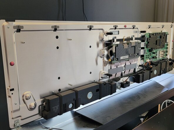
    • Unplug the TV and remove the rear cover

    • The power supply board has large capacitors which may have sufficient charge to cause an electric shock. Therefore wait a few minutes after disconnecting the mains plug before removing the circuit board.

    • Remove the power supply board. Remove the screws and remove the two connectors to the other circuit boards.

  2. LG OLED TV - Power supply board troubleshooting and repair, Check standby voltage: crwdns2935265:02crwdnd2935265:01crwdnd2935265:01crwdne2935265:0
    • To find out whether the power supply unit is basically still working the standby voltage should first be checked

    • As soon as the mains plug is switched on dangerous mains voltage is present at several points. The circuit board should not be touched when plugged in.

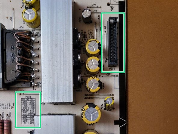
    • Identify socket P201 and measure the voltage between pin 12VM and ground (GND). In standby mode the voltage should be approx. 7.8V.

    • An existing standby voltage of 7.8V does not automatically mean that the power supply board is working correctly. If the voltage is present but not enough current can be supplied to operate the TV in standby mode (red LED lights up) the fault is still with the power supply unit. However this can narrow down the cause.

  3. LG OLED TV - Power supply board troubleshooting and repair, Checking the fuses: crwdns2935265:03crwdnd2935265:01crwdnd2935265:01crwdne2935265:0
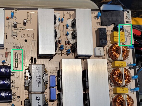
    • There are two fuses on the board. Use a multimeter to check whether both have continuity.

    • If these do not have a continuity they should be replaced with the same type.

  4. LG OLED TV - Power supply board troubleshooting and repair, ICL check: crwdns2935265:04crwdnd2935265:01crwdnd2935265:01crwdne2935265:0
    • If standby voltage is present but the red LED is not lit this could be due to the ICL (Inrush Current Limiter). This limits the current. If this resistance value is too high the current is limited and not enough power can be made available for the other boards

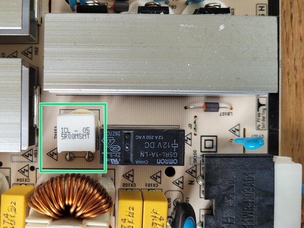
    • Check the resistance directly on the board with a multimeter. The nominal resistance should be 5 ohms. Below 10 ohms should be fine. However if the resistance is in kiloohm range the component is broken and needs to be replaced

    • To check whether this corrects the issue the power supply unit needs be reinstalled and an attempt made to switch the TV on.

  5. LG OLED TV - Power supply board troubleshooting and repair, Visually inspect electrolytic capacitors: crwdns2935265:05crwdnd2935265:01crwdnd2935265:01crwdne2935265:0
    • If electrolytic capacitors are faulty they usually blow up (see photo) or leak. The predetermined breaking point at the top of the capacitor or leaking material in the circuit can be visually inspected.

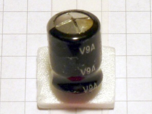
    • Faulty capacitors should be replaced. Make sure to replace capacitors with the same capacitance, tolerance, classification and dielectric strength.

  6. LG OLED TV - Power supply board troubleshooting and repair, Check film capacitors: crwdns2935265:06crwdnd2935265:01crwdnd2935265:02crwdne2935265:0 LG OLED TV - Power supply board troubleshooting and repair, Check film capacitors: crwdns2935265:06crwdnd2935265:02crwdnd2935265:02crwdne2935265:0
    • Inferior film capacitors from "Carli" have been installed in some LG power supply units. These can be recognized by their yellow color (see picture). These lose their nominal capacity relatively quickly.

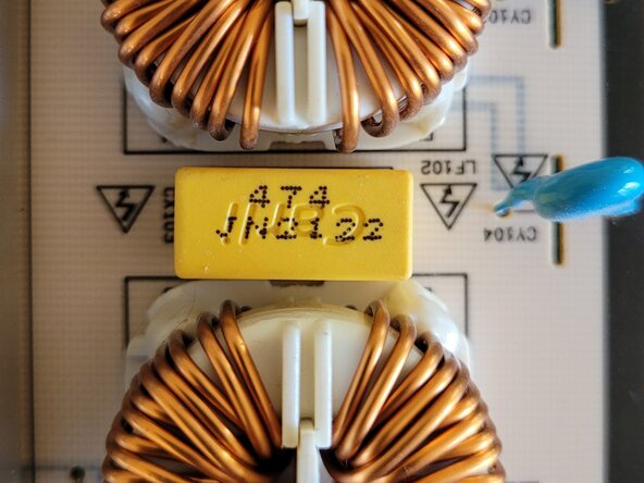
    • In this power supply unit these were only installed as interference suppression capacitors. Input-side 0.47uF capacitors. These do not lead directly to a fault but should be replaced at the same time during a repair.

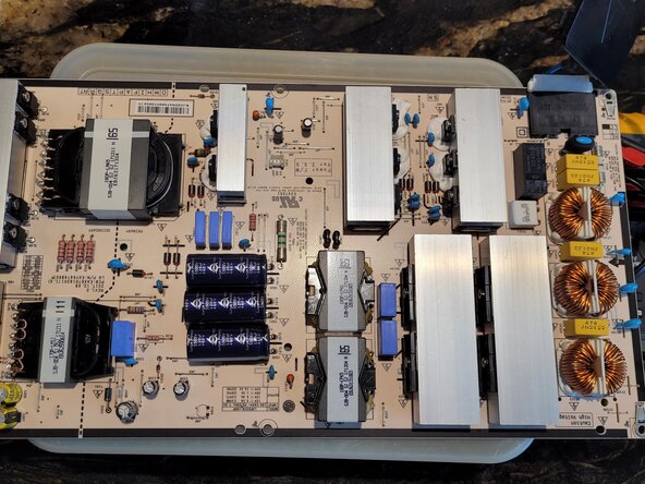
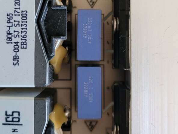
    • If the "Carli" capacitors were not only used on the input side for interference suppression they should be checked or replaced directly. In this circuit these are the blue capacitors as shown in the photo (or similar).

    • To check the remaining capacitance of the capacitors they should be desoldered and the capacitance measured with a multimeter. A deviation of more than 10% is considered faulty. Make sure to replace the capacitors with the same capacitance, tolerance, classification, dielectric strength AC/DC and pin spacing.

crwdns2915888:0crwdne2915888:0

Reinstall the power supply board and attach the cover

crwdns2935227:0crwdne2935227:0

crwdns2934873:0crwdne2934873:0

de en

100%

crwdns2934883:0Computerixcrwdne2934883:0 crwdns2934875:0crwdne2934875:0
crwdns2934877:0crwdne2934877:0 ›

Computerix

crwdns2935283:005/24/23crwdne2935283:0

720 crwdns2915208:0crwdne2915208:0

crwdns2935297:03crwdne2935297:0

crwdns2947412:00crwdne2947412:0

crwdns2917038:0crwdne2917038:0

crwdns2936625:0crwdne2936625:0:

crwdns2936751:024crwdne2936751:0 15

crwdns2936753:07crwdne2936753:0 66

crwdns2936753:030crwdne2936753:0 287

crwdns2942667:0crwdne2942667:0 477