crwdns2915892:0crwdne2915892:0
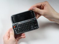
For an easier time working with the LCD Screen, follow the Installation Guide for the Circuit Board and Full Key Board.
crwdns2942213:0crwdne2942213:0
-
-
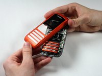
Place the phone so the screen side is facing down.
-
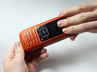
Locate the latch at the end of the phone, opposite of the camera.
-
-
-
Push/pull the latch away from the camera, causing the battery to pop out.
-
-
-
Remove the 5 screw covers on the back of the phone using a Push Pin.
-
-
-
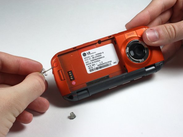
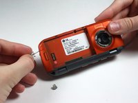
With a Phillips #00 Screwdriver, remove the five 3.44 mm screws that were under the screw covers.
-
Also with a Phillips #00 Screwdriver, remove the screw that was revealed once the battery was removed.
-
-
-
-
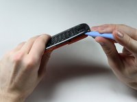
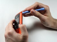
Starting at the card slot or charger port for greater ease, pry off the colored casing from the back of the phone using the Plastic Pry Tool (or a finger nail may work).
-
Remove the back colored casing and set it to the side.
-
-
-
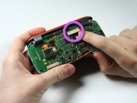
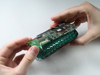
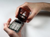
Gently pry and detach the connection located near the hinge with fingers.
-
-
-
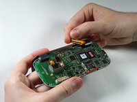
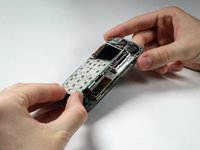
Lift them both out from the rest of the phone.
-
-
-
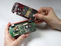
After removing the circuit board and key board, separate the top part with the screen from the bottom part by detaching the hinges.
-
-
-
Remove the 4 screw covers from top piece of phone by using a Push Pin.
-
-
-
Remove the four 3.44 mm screws that were under the covers using a Phillips #00 Screwdriver.
-
-
-
Pry open the colored casing using the Plastic Pry Tool.
-
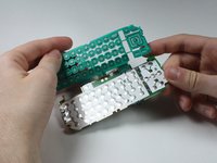
Remove the number pad and place it to the side.
-
-
-
Because the Number Keypad is attached on one side and on top of the outer screen, open its metal casing, in a "door-opening" manner.
-


To reassemble your device, follow these instructions in reverse order.
To reassemble your device, follow these instructions in reverse order.
crwdns2935221:0crwdne2935221:0
crwdns2935229:02crwdne2935229:0
crwdns2915084:0crwdne2915084:0

Cal Poly, Team 15-15, Forte Spring 2012 crwdns2935289:0Cal Poly, Team 15-15, Forte Spring 2012crwdne2935289:0
CPSU-FORTE-S12S15G15
crwdns2931471:05crwdne2931471:0
crwdns2935297:08crwdne2935297:0