crwdns2915892:0crwdne2915892:0
In this guide, you will learn how to remove and replace the motherboard of your Kodak PixPro AZ251. Replacing the motherboard may be necessary if your camera does not turn on and you already tried replacing the batteries. For this replacement guide you should be comfortable using a soldering iron.
crwdns2942213:0crwdne2942213:0
-
-
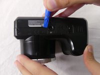
Slide switch to open lock position.
-
-
-
Press down on the battery cover and slide outwards to open.
-
-
-
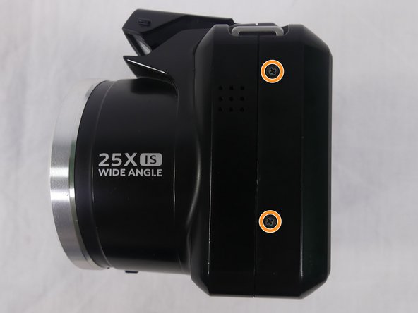
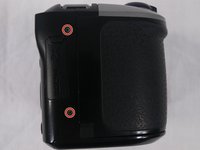
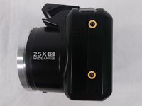
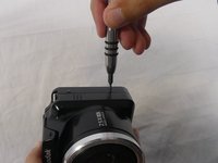
Remove a total of four 5mm JIS #000 screws from around the camera:
-
Two screws from the right side.
-
Two screws from the left side.
-
-
-
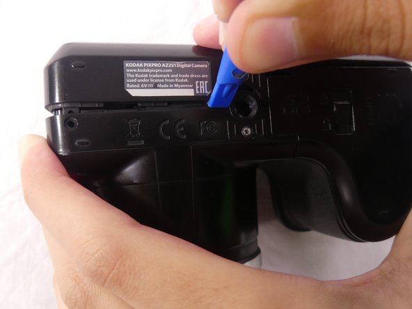
Remove the single 5mm Phillips #00 screw from the bottom.
-
-
-
Open the flash module.
-
Remove the two 6mm JIS #00 screws found inside of the flash housing.
-
-
-
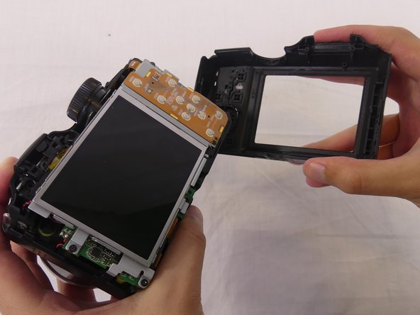
Use a plastic opening tool to pry apart both halves of the camera.
-
Remove the back panel.
-
-
-
-
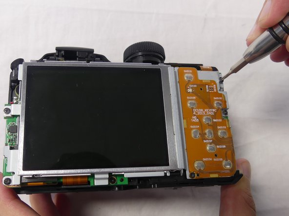
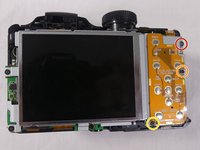
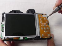
Remove these three JIS #000 screws from the control board:
-
5mm screw.
-
4mm screw.
-
2mm screw.
-
-
-
Pull the small metal switch plate to the side.
-
-
-
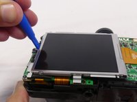
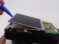
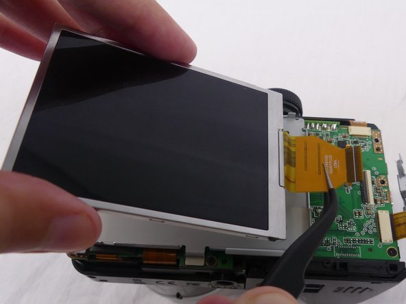
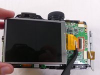
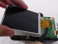
Pry the LCD screen out of the metal housing plate with a plastic opening tool.
-
-
-
Use a spudger to flip up the retaining flap on the display ribbon cable ZIF socket.
-
Pull the orange cable out of the socket.
-
-
-
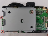
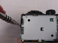
Remove three 4mm JIS #000 screws from the metal housing plate.
-
-
-
Lift the metal housing plate out using your hands.
-
-
crwdns2935267:0crwdne2935267:0Tweezers$4.99
-
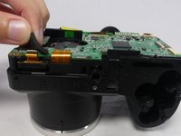
Disconnect the orange cable, connecting the small metal switch plate to the motherboard, by pulling it outwards with tweezers.
-
-
-
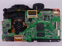
Disconnect two orange cables, one at the top and the other at the bottom of the motherboard, by pulling them outwards with tweezers.
-
Use a spudger to flip up the retaining flap on the ribbon cable ZIF socket.
-
-
-
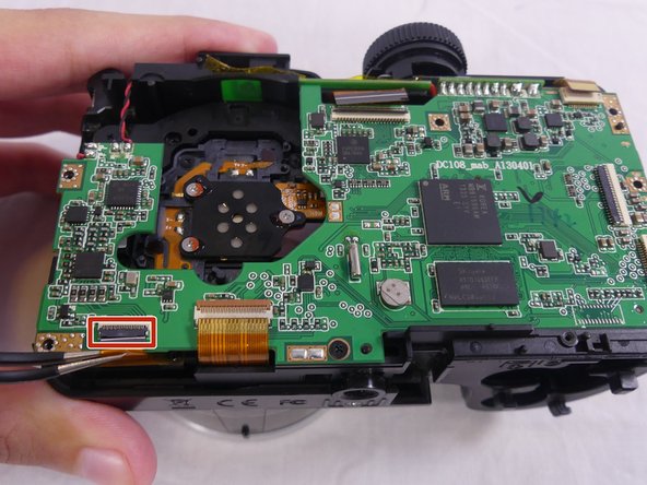
Remove the rectangular black cushion pad on the bottom left of the motherboard by pulling it upwards with your hands.
-
Use a spudger to flip up the retaining flap on the ribbon cable ZIF socket.
-
Disconnect the orange cable by pulling it outwards with tweezers.
-
-
-
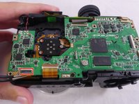
Remove the two 4mm JIS #000 screws from the motherboard.
-
-
-
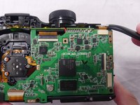
Desolder two pairs of electrical cable connections on the top left of the motherboard using the soldering iron.
-
Desolder the metal connector joining the two parts of the motherboard using the soldering iron.
-
-
-
Lift the motherboard up using your hands.
-


To reassemble your device, follow these instructions in reverse order.
To reassemble your device, follow these instructions in reverse order.
crwdns2935221:0crwdne2935221:0
crwdns2935229:05crwdne2935229:0
crwdns2915084:0crwdne2915084:0

USF Tampa, Team S1-G1, Cagle Spring 2018 crwdns2935289:0USF Tampa, Team S1-G1, Cagle Spring 2018crwdne2935289:0
USFT-CAGLE-S18S1G1
crwdns2931471:04crwdne2931471:0
crwdns2935297:07crwdne2935297:0