crwdns2915892:0crwdne2915892:0
In this guide, you will replace the water sensor. This is necessary if the sensor is faulty and doesn't accurately read the amount of water in the Water Reservoir.
crwdns2942213:0crwdne2942213:0
-
-
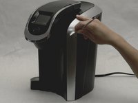
Locate and grab the Water Reservoir with your hands.
-
-
-
Lift the Water Reservoir up. It should be easy to separate it from the main part of the brewer.
-
-
-
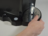
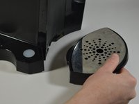
Remove the Drip Tray by pulling it out of the device.
-
-
-
Using the Phillips #1 screwdriver, remove the six 140mm screws from the bottom of the Keurig machine.
-
-
-
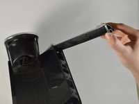
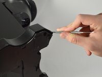
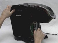
Use the metal spudger to separate the silver panel on the right side of the Keurig machine.
-
Tilt the brewer upside down and grab the bottom of the silver panel
-
Using your hands, peel off the silver panel from the Keurig machine.
-
-
-
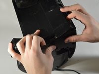
With one hand, place one finger inside the frame where the silver panel was attached and hold the base.
-
With the other hand, pull down to pop out the front housing of the Keurig machine.
-
-
-
-
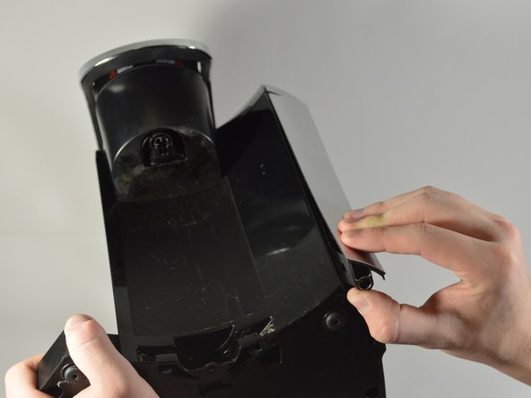
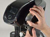
Using your hands, pry the back exterior of the brewer from the right side of the Keurig.
-
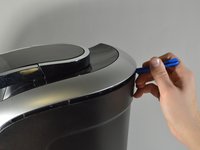
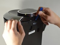
Use the blue opening tool to separate the top right silver panel from the back exterior.
-
-
-
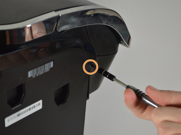
Use the Phillips #1 screwdriver to remove the 120mm screw located on the top left corner from the side of the brewer where the water reservoir was.
-
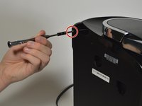
Use the Phillips #1 screwdriver to remove a 140mm screw located under the end of the empty slot running across the left side of the Keurig.
-
-
-
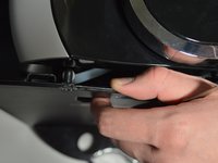
Separate the side panel from the top frame of the brewer, using the blue opening tool for help if necessary.
-
-
-
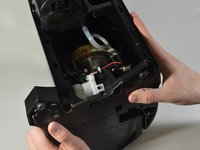
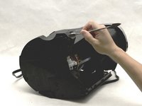
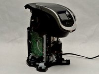
Place the brewer on its side as shown in the picture
-
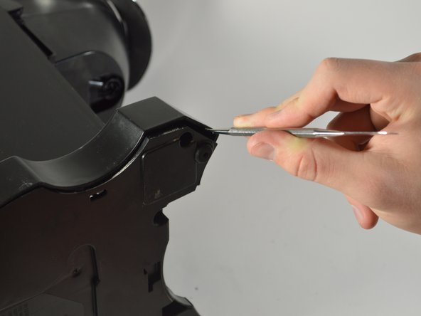
Using the metal spudger, pry away the housing surrounding the sides of the Keurig machine from the bottom.
-
Work your way around the perimeter of the base.
-
-
-
Remove the entire back exterior surrounding the Keurig by removing the latches connecting the back exterior to the silver frame on top. To do this, use the metal spudger to lift the latches up and out.
Why are steps 12 through 15 required? It doesn't seem like they are needed to perform the final step, as the sensor and connector on the opposite side are both accessible at this point.
-
-
-
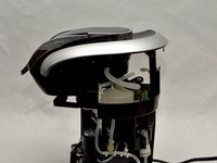
Reorient the brewer as shown in the picture.
-
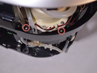
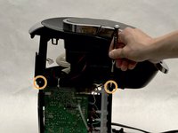
Locate the four 140mm screws holding the top frame of the Keurig in place. Remove these screws using the Phillips #1 screwdriver.
-
Two of the screws are on the inside of the frame close to the water heater.
-
The other two screws are located on the outside of the frame.
-
-
-
Remove the top of the framing that encases the circuit board.
-
Remove the wires that are connected to the top of the circuit board.
-
Pull out the multicolored wires by their bases.
-
The bundle with black wires and one red wire is connected to the very top of the circuit board. To remove these wires, squeeze in the white tabs as you pull them out.
-
-
-
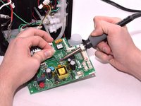
Using the metal spudger, snap the circuit board out of the latches on the bottom of the board.
-
-
-
Unplug the rest of the wires connecting to the circuit board by pulling them out by their bases.
-
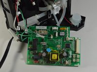
Remove the circuit board from the device.
Good day. What is the value/details of the MOV1 (metal-oxide varistor)? Thanks in advance.
Also want to know this capacitor part number. My one burnt out…
Excellent photos, especially of circuit board. Thanks! I am curious what manner of beast U1 is: FPGA, micro controller and/or any details. It’s been while since I worked on such control circuits and rarely mass-produced items so choices are different. BTW I cam here trying to troubleshoot why the clock is randomly reset, even in the absence of power failure. I can buy a cheap similar unit - not quite yet, at a thrift store if I wanted to replace the entire board.
The only things i know from the varistor : It’s from littelfuse and what’s printed on the varistor is LF9 P1505 1638 (on my K550 with a K543 MAIN BOARD) but no clue for real part number.
I would love to get my hands on a circuit diagram for this board. What do VR1 and VR2 do? Is one of them a control for the sensitivity of the pressure switch FPN-15PG that shuts the system down if the pump pressure gets too high indicating a possible clogged dispenser pin? The VR would go between pins 1 and 6 and be about 200 ohms max.
-
-
-
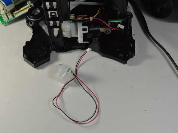
Pull out the white tab that has the wires that connect the Water Sensor to the water pump.
-
-
-
Pry the water sensor out of the frame on the base of the brewer and remove it from the device.
-


To reassemble your device, follow these instructions in reverse order.
To reassemble your device, follow these instructions in reverse order.
crwdns2935221:0crwdne2935221:0
crwdns2935227:0crwdne2935227:0
crwdns2915084:0crwdne2915084:0

Cal Poly, Team S24-G8, Maness Spring 2018 crwdns2935289:0Cal Poly, Team S24-G8, Maness Spring 2018crwdne2935289:0
CPSU-MANESS-S18S24G8
crwdns2931471:04crwdne2931471:0
crwdns2935297:010crwdne2935297:0
crwdns2947410:01crwdne2947410:0
Can I buy a replacement water sensor directly from you? If not, where can I buy one?