crwdns2915892:0crwdne2915892:0
If your KBParadise V80 TKL Mechanical Keyboard with alps key switches isn’t registering key presses or registering double/triple clicks when you try to type, use this guide to replace the key switch.
Key switches are used to detect input when a user clicks a button on a keyboard. A worn/faulty key switch will possibly not register clicks, or send repeated clicks.
Before using this guide, identify all the key switches needing replacement, noting which keys need replacing. Possibly try using different mini-usb cables to make sure the issue is not related to cross talk in the cable.
Before beginning, make sure to remove the mini-usb cable.
crwdns2942213:0crwdne2942213:0
-
-
Insert the key cap puller into the cracks around the keycap.
-
Twist the tool around the bottom of the keycap.
-
Hold the keyboard down, and pull on the keycap slowly.
-
Pull up as straight as possible.
-
-
-
Proceed to remove the surrounding keycaps.
-
-
-
Flip the keyboard over so that the bottom is facing upward.
-
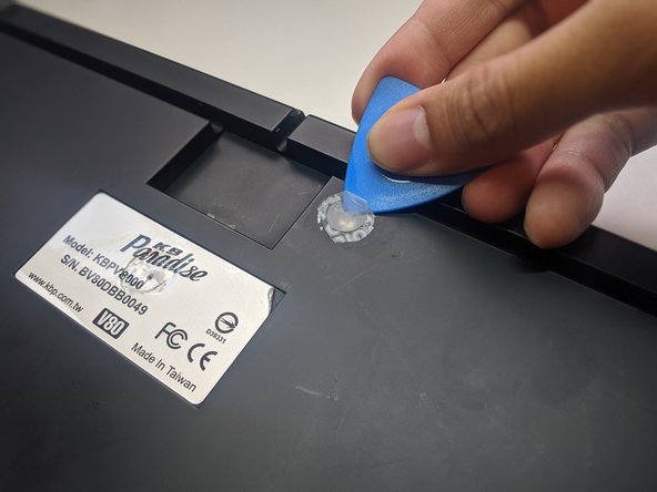
Slip an opening pick beneath the warranty sticker.
-
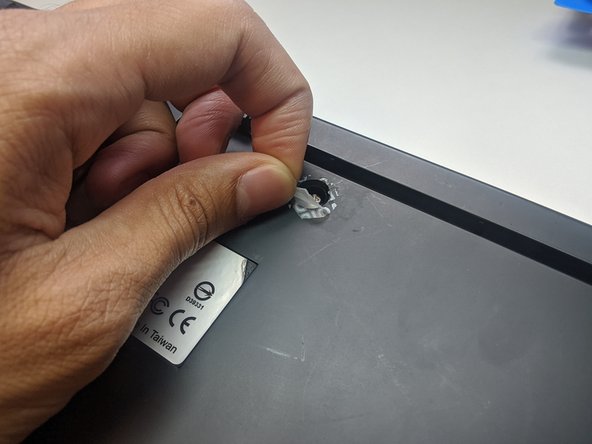
Proceed to pull the sticker off to reveal the hole.
-
-
-
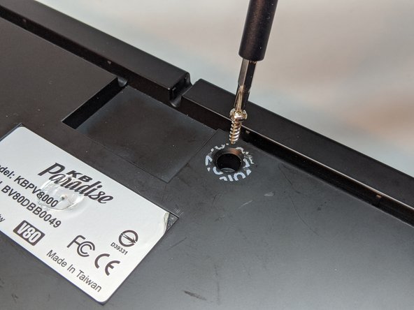
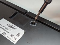
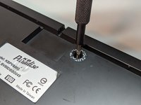
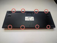
Use a Phillips #1 Screwdriver to remove the 10 mm screw.
-
-
-
-
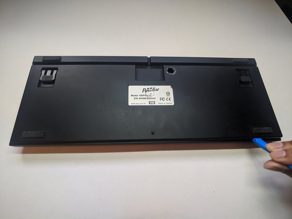
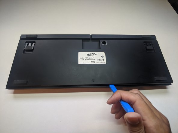
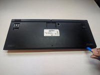
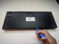
Slip an opening tool into the cracks at the indicated points.
-
Pry open carefully.
-
-
-
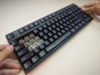
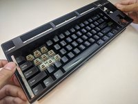
Flip the keyboard so that the keys are facing upward.
-
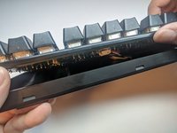
Grab the sides of the top case and pull up gently.
-
-
-
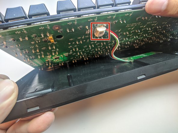
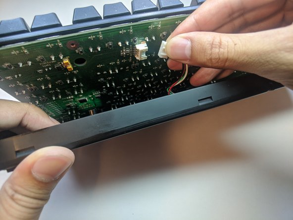
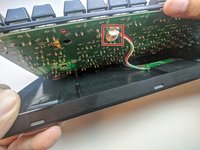
Separate the plate from the bottom case slightly.
-
Reach within and remove the daughterboard cable.
-
-
-
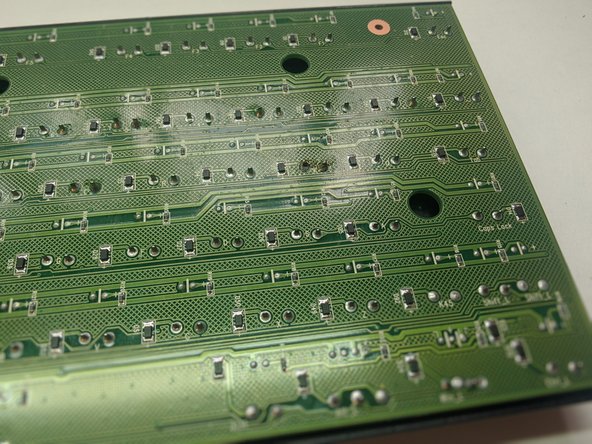
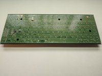
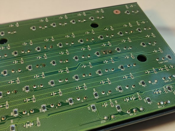
Turn the plate over.
-
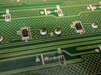
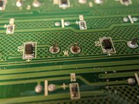
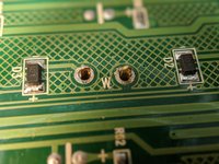
Locate the pins for the key switch.
-
-
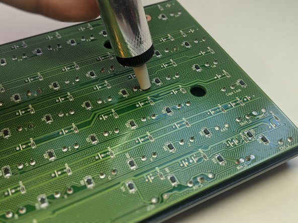
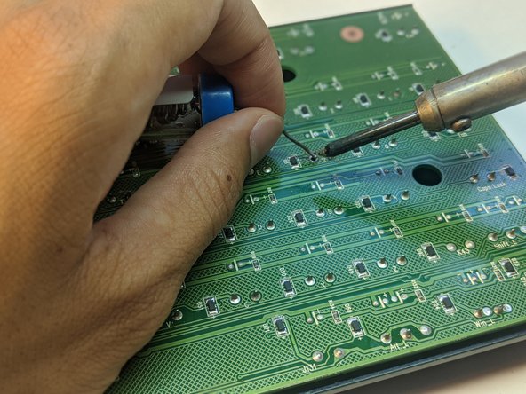
crwdns2935267:0crwdne2935267:0Desoldering Pump$3.99
-
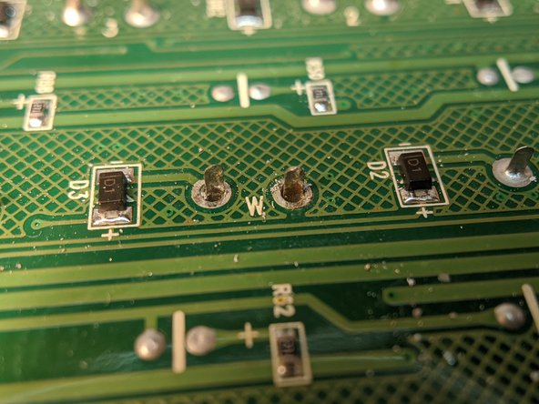
Desolder the pins with a soldering iron and a desoldering pump.
-
Repeat until the pins freely move inside the wells without heat.
-
-
-
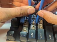
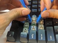
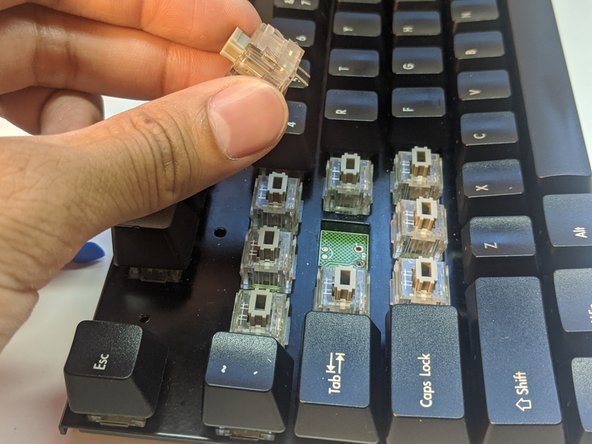
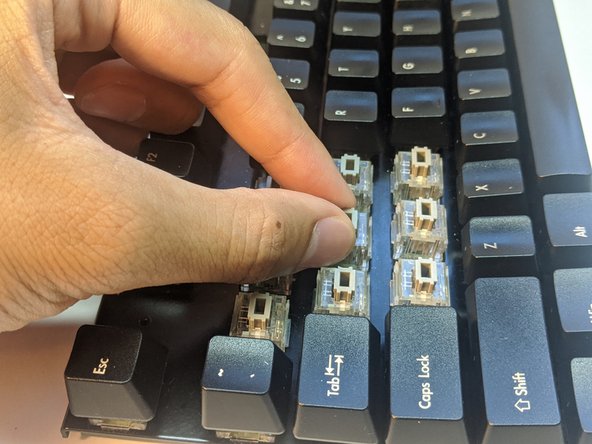
Wedge two opening tools under the key switch.
-
Pull up gently.
-
-
-
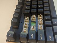
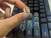
Insert a new key switch into the well with pins corresponding to that of the PCBs.
-
-
-
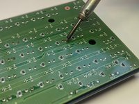
Solder the pins onto the PCB ensuring the solder stays within the wells of the pins.
-


To reassemble your device, follow these instructions in reverse order starting at step 7.
To reassemble your device, follow these instructions in reverse order starting at step 7.
crwdns2935221:0crwdne2935221:0
crwdns2935229:02crwdne2935229:0

crwdns2915084:0crwdne2915084:0

York University, Team S1-G40, Allen Summer 2020 crwdns2935289:0York University, Team S1-G40, Allen Summer 2020crwdne2935289:0
YORK-ALLEN-SU20S1G40
crwdns2934841:01crwdne2934841:0
crwdns2935297:02crwdne2935297:0