crwdns2915892:0crwdne2915892:0
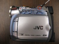
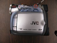
This is a step-by-step guide to replace an LCD screen in a JVC GR-D290U camera.
crwdns2942213:0crwdne2942213:0
-
-
Remove the camera battery. (Not shown.)
-
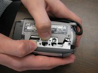
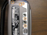
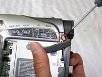
Remove the 2 screws connecting the back plate to the camera base.
-
-
-
Remove the 2 screws on the side opposite the LCD screen.
-
-
-
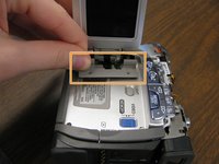
Lift up the dark gray tab on the LCD side of the camera and move it aside.
-
Remove the screw under the dark gray tab and then replace the tab.
-
-
-
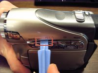
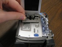
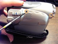
Place a plastic opening tool under the seam of the camera top cover and unsnap the cover.
-
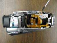
Pull the top cover off of the camera base and set aside.
-
-
-
Remove the 2 screws underneath the top cover on the LCD side of the camera.
-
-
-
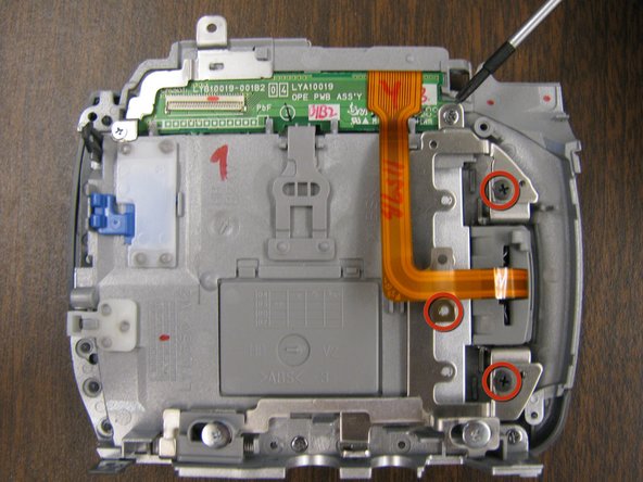
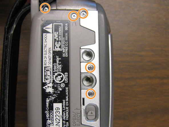
Remove the 5 screws indicated on the bottom plate of the camera.
-
-
-
Open the LCD screen and remove the 2 screws at the hinge of the screen.
-
Remove the plastic hinge cover from the camera base.
-
Close the LCD screen when finished.
-
-
-
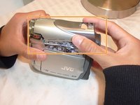
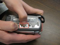
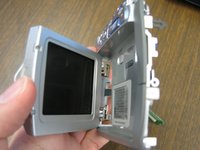
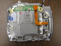
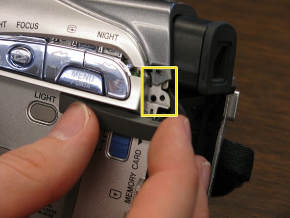
Start from the bottom of the camera. Press and hold the eject button with one hand.
-
Use your other hand to pry the LCD screen cover from the base. Leave the labeled side closed.
-
-
-
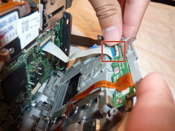
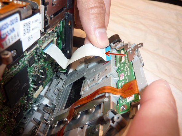
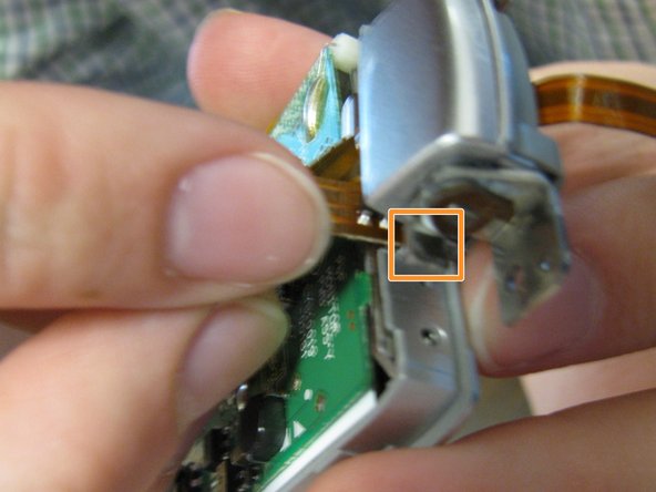
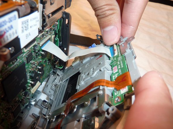
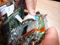
Detach the white tab from the LCD screen side of the camera by gently tugging at the base of the tab.
-
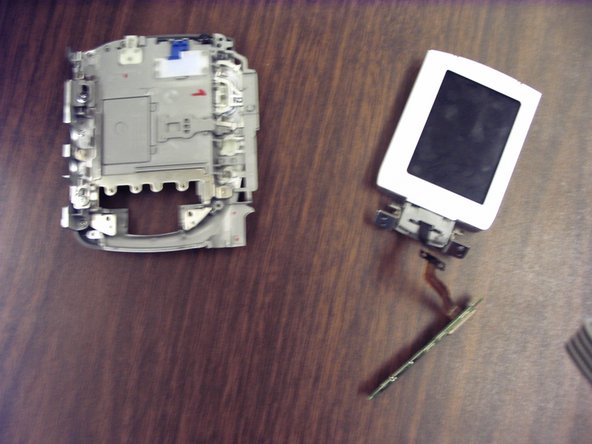
Put the larger camera base aside.
-
-
-
-
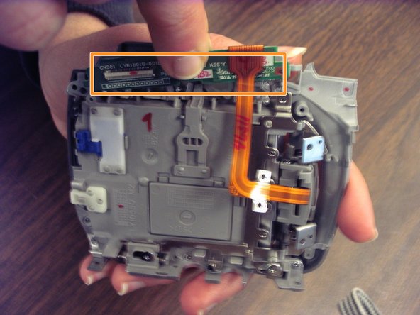
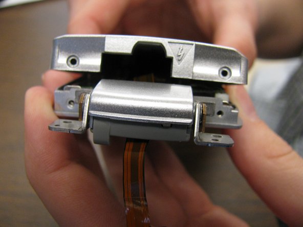
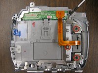
Remove the 3 screws holding the LCD screen hinge to the base.
-
-
-
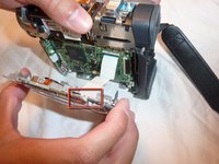
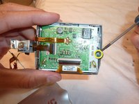
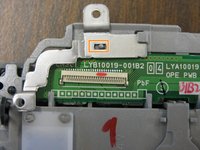
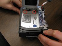
Remove the 2 screws on the green circuit board.
-
-
-
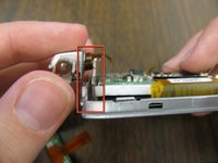
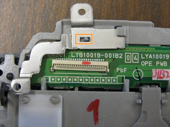
Remove the L-shaped metal piece from the upper left-hand corner of the circuit board.
-
Remove the circuit board from the cover piece and move it aside with the orange band intact.
-
-
-
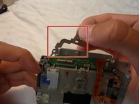
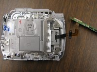
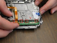
Open the LCD screen and carefully pull the circuit board through the empty hinge space.
-
Set aside the larger LCD panel.
-
-
-
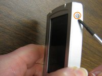
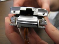
Remove the 2 screws on the hinge side of the LCD screen.
-
Remove the screw at side of the LCD screen.
-
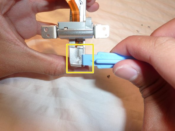
Pull it open with a plastic opening tool and pry it apart.
-
-
-
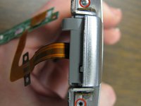
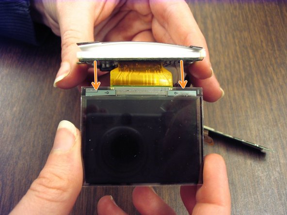
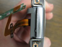
Remove the screw in the circuit board.
-
Pull the LCD screen pack from the frame with the circuit board on top.
-
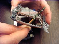
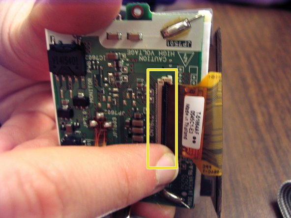
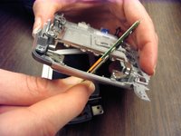
Detach the LCD screen by firmly grasping the copper tab and gently tugging until the latch unsnaps.
-
-
-
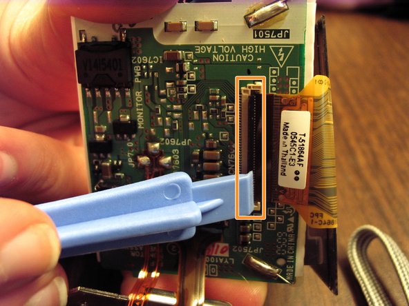
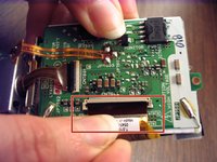
Connect the new LCD screen by fitting in the copper attachment site to the thin, black clasp on the circuit board.
-
Fold over the black clasp and snap it into place.
-
-
-
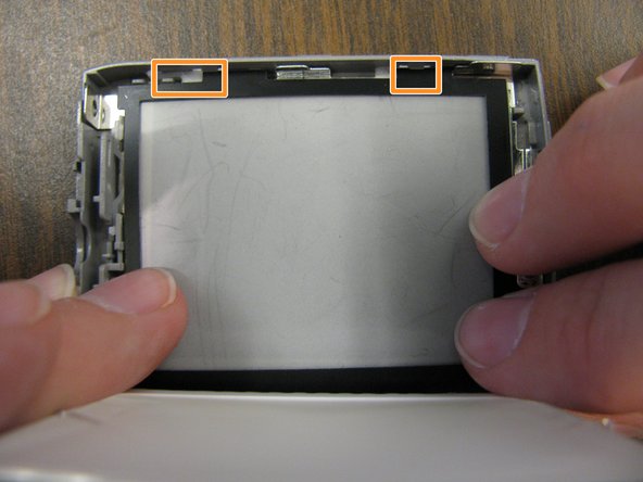
Put the LCD screen into the silver frame and make sure it lies flat. It should line up with the two white plastic brackets.
-
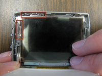
Place the black film frame lined up with the white film into the silver frame. Both should be held in place by tabs.
-
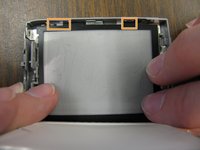
Place the circuit board over the film layers.
-
Screw in the circuit board to the frame.
-
Double-check that the LCD screen lies flat in its frame and reinsert the circuit board screw.
-
-
-
Before reattaching the LCD screen lid, make sure the silver hinge piece is inserted in the slot next to the circuit board.
-
Replace the loose orange band in the slot on the hinge side of the LCD screen.
-
Snap the LCD screen lid back in place starting at the side opposite the hinge.
-
-
-
Reinsert the shortest of the 3 screws on the top of the screen cover opposite of the hinge.
-
Reinsert the 2 remaining screws on the hinge side of the LCD screen.
-
-
-
Place the loose circuit board back through the empty hinge space.
-
Line up the LCD screen in slot on the camera base and snap it into place.
-
Reinsert the 3 screws along the orange band to hold the LCD screen onto the entire panel.
-
-
-
Reinsert the circuit board into the slot. Make sure to lock it securely under the tabs.
-
Reinsert the L-shaped metal piece into its slot. Line it up with the screw hole and the protruding place holder.
-
Reinsert the 2 screws in the circuit board with the longer screw holding the L-shaped metal piece in place.
-
-
-
Reattach the white tab by placing it under the thin, black slot and snap it back into place.
-
Carefully line up the bottom of the LCD panel and the camera base, then snap it back into place.
-
-
-
Reinsert the LCD screen hinge and screw in the 2 screws to hold it in place
-
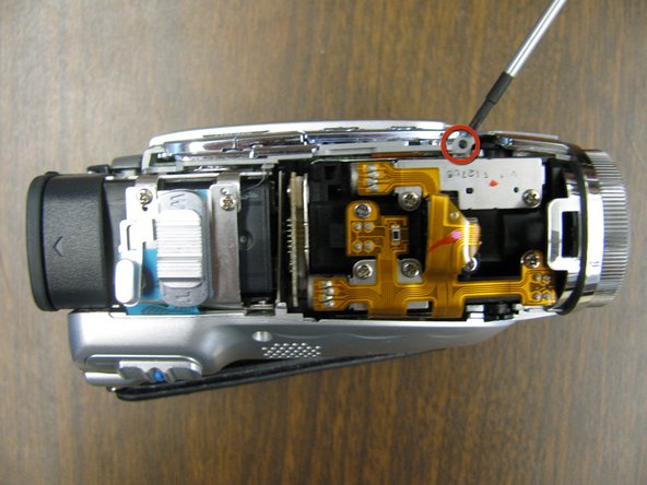
Reinsert the 5 screws on the bottom panel of the camera. The shortest screw needs to be put into the hole with the arrow pointing to it.
-
-
-
Reinsert the 2 screws under the top cover of the LCD side of the camera.
-
Move the dark grey tab to ensure that the top cover is not damaged.
-
Line up the top cover on the camera base and then snap it back into place.
-
-
-
Reinsert the screw under the dark, grey tab on the LCD side of the camera and replace tab.
-
Reinsert the 2 screws on the side of the camera opposite of the LCD screen.
-
-
-
Reinsert the 2 screws connecting the back plate to the camera base.
-


crwdns2915084:0crwdne2915084:0

Cal Poly, Team 18-69, Johann Spring 2010 crwdns2935289:0Cal Poly, Team 18-69, Johann Spring 2010crwdne2935289:0
CPSU-JOHANN-S10S18G69
crwdns2931471:04crwdne2931471:0
crwdns2935297:03crwdne2935297:0