crwdns2915892:0crwdne2915892:0
This guide will walk you through from taking apart the device, disconnecting all the cables inside and taking out the I/O board in order to replace the auxiliary port.
crwdns2942213:0crwdne2942213:0
-
-
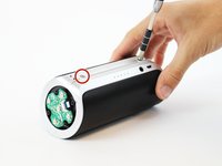
Begin by removing the rubber caps on both sides of the JBL Flip 2 by using the black spudger to get in between the creases.
-
-
-
Remove the eight 7.0 mm Phillips #1 screws on both sides of the JBL Flip 2.
-
-
-
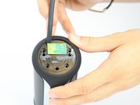
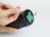
The NFC chip is glued onto the side of the device. Use the black spudger to separate the mic from the surface.
-
Gently slide the NFC chip into the device through the slot that the wire comes from.
-
-
-
Peel the black rubber piece from one end to the other.
-
-
-
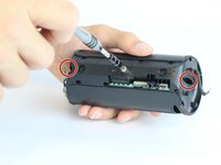
Remove the two 7.0 mm Phillips #1 screws.
-
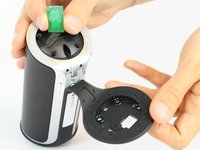
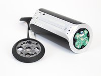
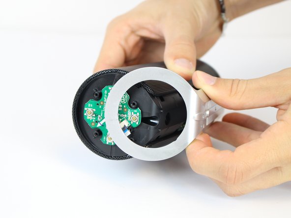
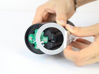
Carefully detach the silver plastic cover by pulling both ends off.
-
Separate the silver plastic piece by pulling it off from the middle.
-
-
-
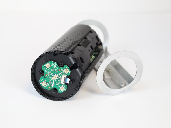
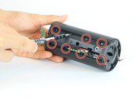
Using a flat-head screwdriver or spudger, pry out the 8 metal nibs on the back side of the speaker.
-
Repeat the same process for the 4 remaining metal nibs (two on each end).
-
-
-
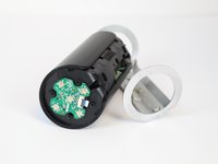
Expand the metal casing and carefully slide it off the speaker.
-
-
-
-
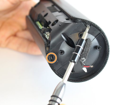
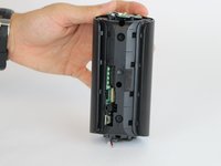
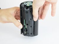
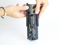
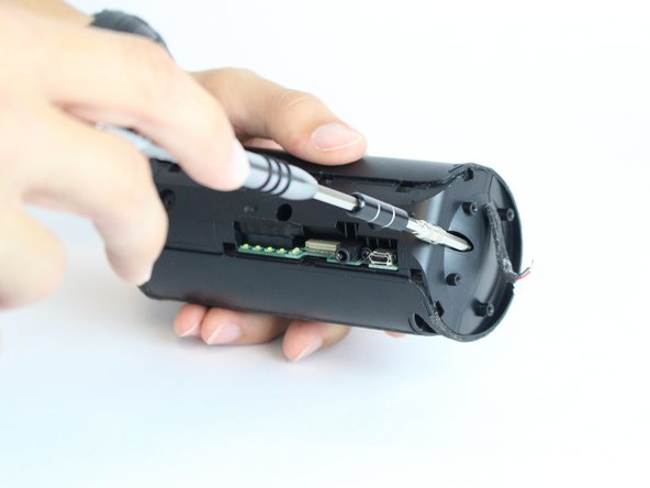
Using the driver adapter, first insert the #4 socket into the driver; followed by the #1 Philip's head bit in order to reach the three 13.0 mm screws.
-
-
-
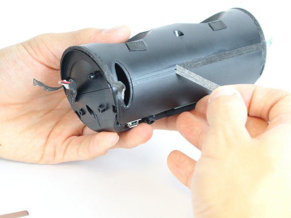
Using the classic spudger, get underneath the black tape strips found on both side of the device.
-
After lifting a portion of the tape off of the device, gently peel the tape off of the device, making sure to keep it intact.
-
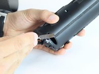
There is another piece of tape on the side of the device with the control buttons. Lift the tape with the classic spudger and then peel the rest of the tape off.
-
-
-
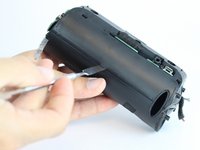
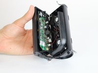
Wedge a spudger between the two halves where the tape was to pry the device open.
-
-
-
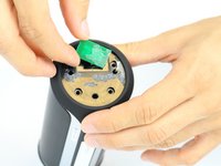
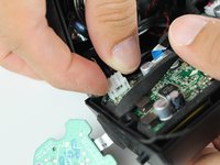
Use the black spudger to disconnect the speaker cord from it's socket.
-
-
-
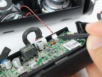
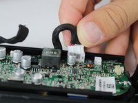
Use the black spudger to disconnect the auxiliary wire from its socket.
-
-
-
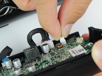
Carefully remove the cable connecting the control chip to the motherboard.
-
-
-
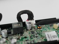
Using the black spudger, carefully remove the cord connecting the battery to the motherboard.
-
-
-
Carefully remove the cable connecting the nfc chip to the motherboard.
-
-
-
Remove the one 7.0 mm Phillips #1 screw that connects the I/O board to the casing.
-
-
-
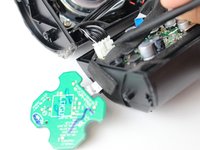
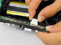
Remove the cord that connects the I/O board to the motherboard.
-
Put the motherboard to the side.
-
-
-
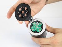
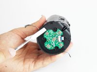
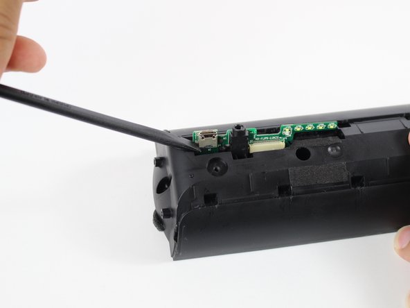
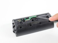
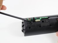
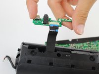
With the black spudger, carefully wedge out the I/O board.
-
-
-
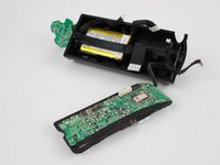
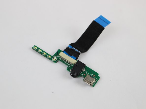
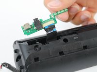
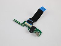
Gently pull the I/O board out from the speaker.
-
-
-
Desolder the auxiliary port to remove it from the I/O board..
-


To reassemble your device, follow these instructions in reverse order.
To reassemble your device, follow these instructions in reverse order.
crwdns2935221:0crwdne2935221:0
crwdns2935227:0crwdne2935227:0
crwdns2915084:0crwdne2915084:0

USF Tampa, Team 11-2, Cheng Spring 2016 crwdns2935289:0USF Tampa, Team 11-2, Cheng Spring 2016crwdne2935289:0
USFT-CHENG-S16S11G2
crwdns2931471:04crwdne2931471:0
crwdns2935297:010crwdne2935297:0
crwdns2947412:02crwdne2947412:0
Is It hard to repair ? I have one that is not charging, I don't know if is the battery or the usb port.
Where can I purchase the auxiliary port (preferably in Europe)?