crwdns2956850:0crwdne2956850:0 crwdns2956756:0crwdnd2956756:0crwdne2956756:0
crwdns2915892:0crwdne2915892:0
This guide explains how to assemble an Infinity PC: mounting the chassis and Kontron motherboard into the housing, installing the CPU and heat sink, wiring the button board, LED, and cooling fans, and then adding the SSD and Wi-Fi card.
crwdns2942213:0crwdne2942213:0
-
-
-
Screw the 3 skeleton pieces in place using 8 M3x6 Torx screws.
 crwdns2952109:0crwdne2952109:0
-
-
-
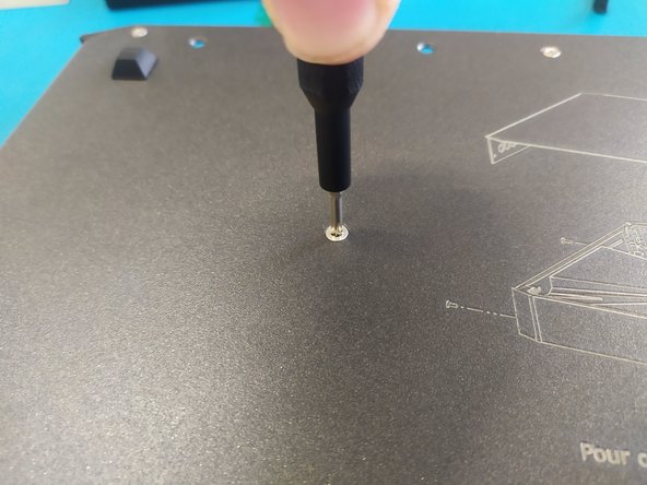
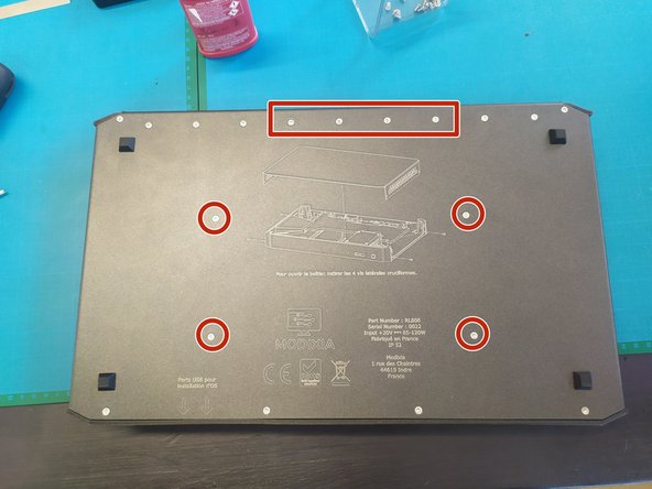
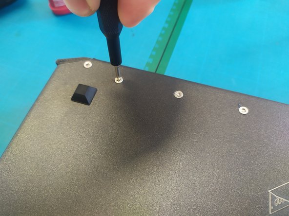
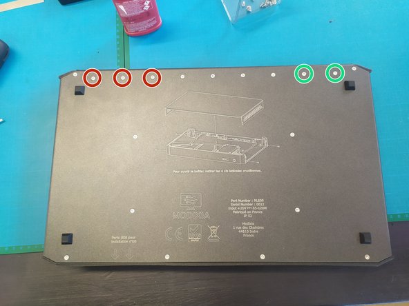
Drive 2 M3x6 Phillips screws into the metal sheet inserts.
-
-
-
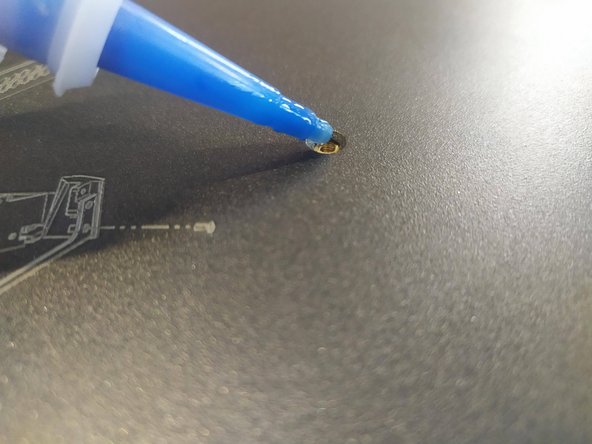
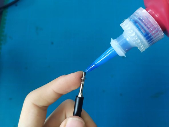
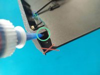
Add a drop of threadlocker into the inserts.
-
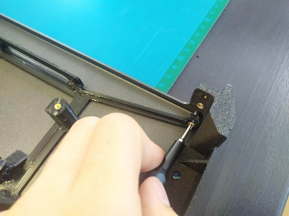
Drive 2 M3x6 Torx screws into the right block.
-
Drive 3 M3x6 Torx screws into the left block.
-
-
-
Apply a drop of threadlocker.
-
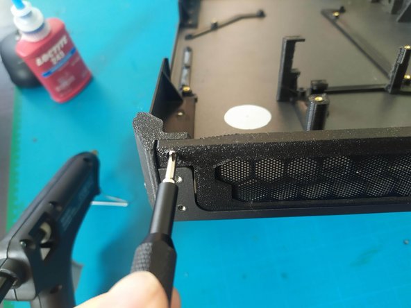
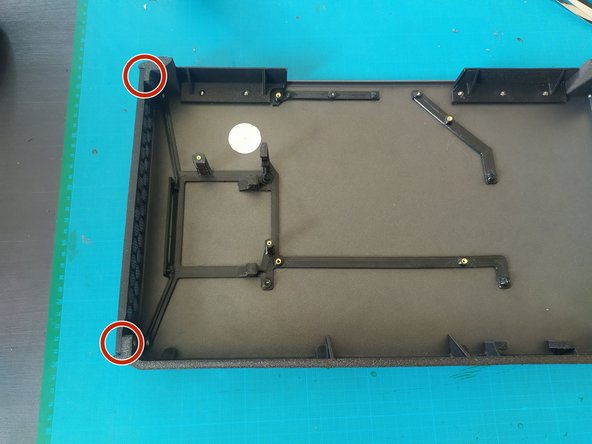
Secure the anti-dust mesh with 2 Phillips M2x5 screws.
-
-
-
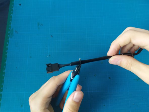
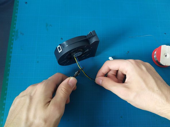
Cut the female connector off of a cooling fan extension cable.
-
Remove the label from the extension.
-
-
-
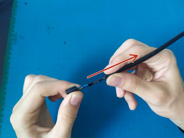
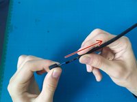
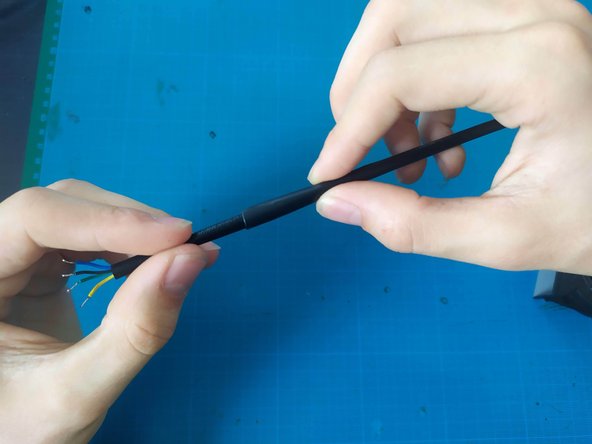
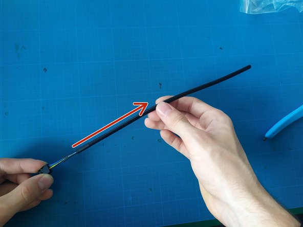
Slide the outer sleeve back about 3 cm.
-
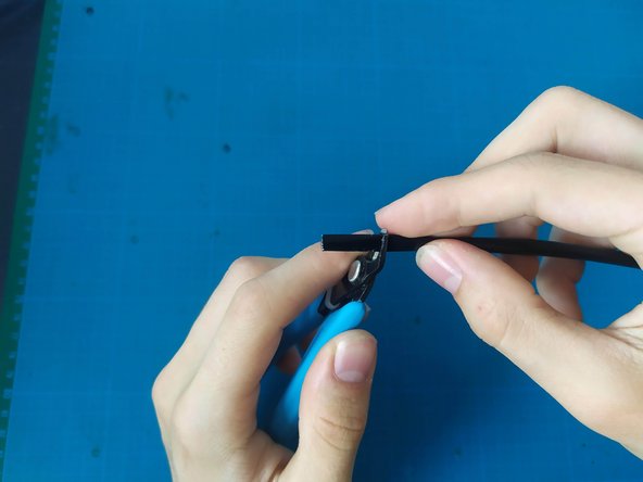
Cut about 2 cm off the outer sleeve.
-
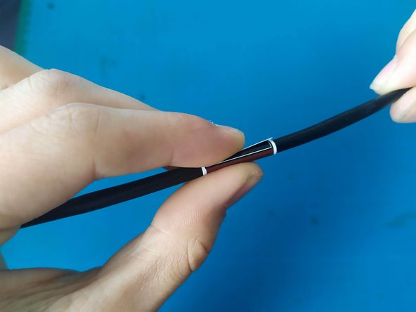
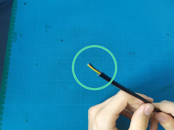
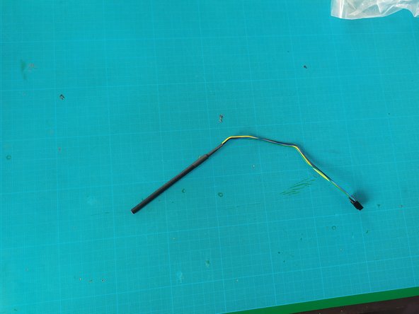
When putting the sleeve back in place, you should get this.
-
-
-
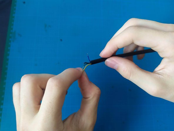
Strip the wires.
-
Twist the exposed part.
-
Tin the wires.
-
-
-
Cut the original connector so that 2-3 cm of wire remains.
-
Strip, twist, and tin the wires.
-
Slide heat shrink tubing over the outer casing.
-
As well as over each individual wire.
-
-
-
Solder the wires.
-
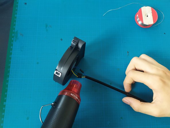
Heat the small heat-shrink tubing with the heat gun.
-
Then [apply heat to] the large one; it must cover the small ones as much as possible.
-
-
-
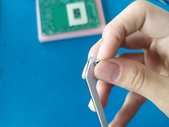
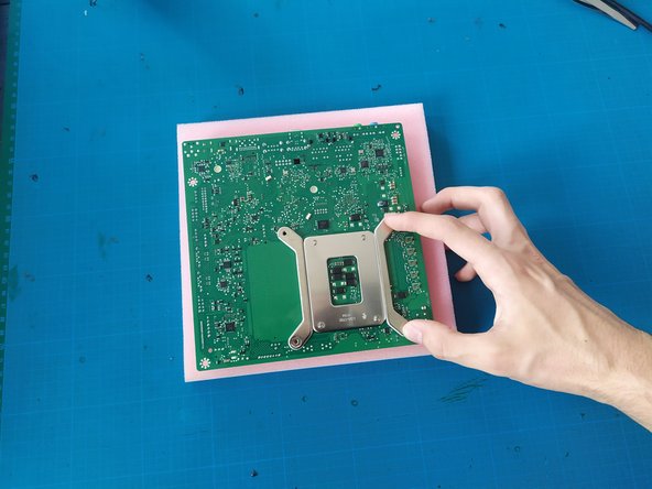
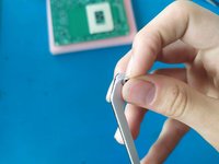
Remove the film from the heat sink fastener.
-
Stick the fasteners under the motherboard.
-
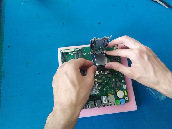
Gently lift the retention lever to open the socket.
-
-
-
Gently place the CPU into the socket. It should seat without force. If you feel resistance, check the alignment and try again.
-
Once the CPU is in place, lower the retention lever to secure the CPU in the socket.
-
-
-
-
Apply a thin layer of thermal paste to the top of the CPU, if you have not already done so.
-
Place the heat sink on the CPU and secure it by tightening the screws.
-
-
-
Install the backplate.
-
Install the motherboard.
-
-
-
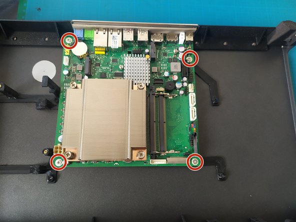
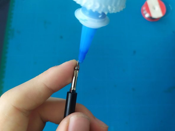
Apply a drop of threadlocker to each screw.
-
Install 4 M3x6 Torx screws.
-
-
-
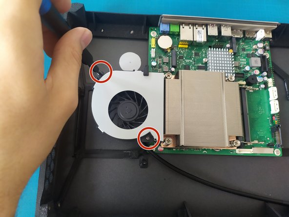
Apply a drop of threadlocker to each screw.
-
Drive two 2 mm Phillips screws.
-
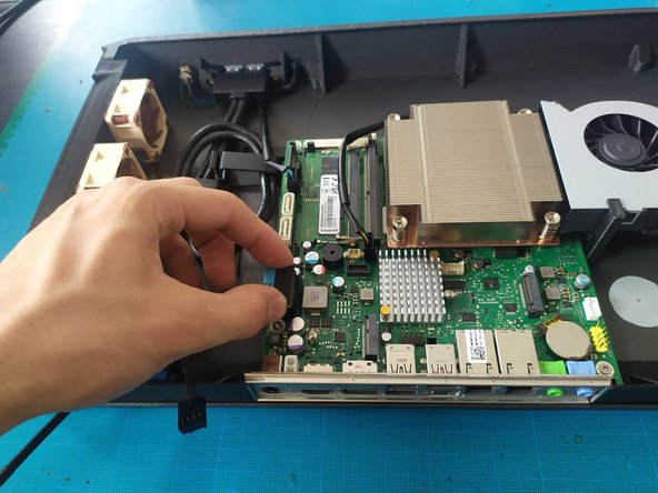
Connect the cooling fan.
-
-
-
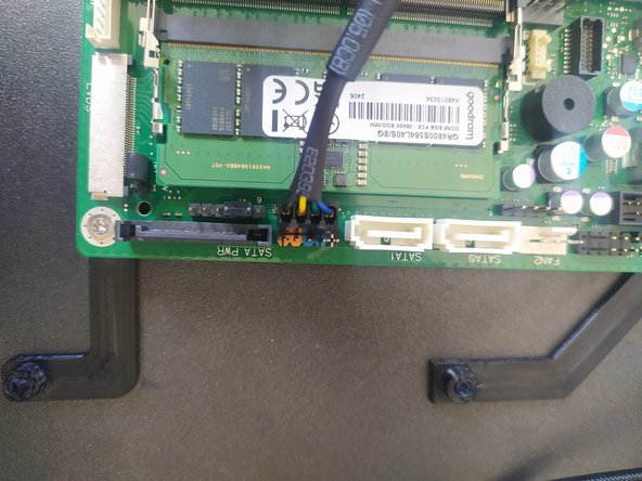
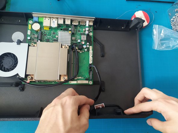
Connect a cooling fan extension to the socket (see photo).
-
Estimate the required cable length.
-
-
-
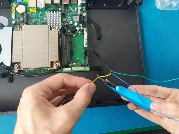
Cut the black cable so that 25 cm remains.
-
Slide the outer sheath back to cut it by 7 cm without cutting the wires.
-
-
-
Cut the yellow and black wires so there is about 2 cm of wire outside the sheath.
-
Strip, twist, and tin the yellow and black wires.
-
-
-
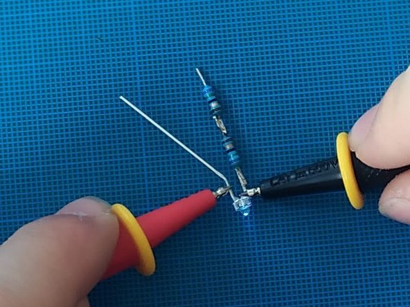
Solder 2 75-ohm resistance in series to the short leg of the LED as shown in the photo.
-
Before proceeding to the next step, please test the LED. To do this, use the multimeter in continuity test mode with the positive probe on the long leg and the negative probe on the short leg. If the LED lights up, it is working.
-
Slide a piece of heat shrink tubing onto the yellow wire.
-
Solder the LED, with the negative terminal on the yellow wire and the positive terminal on the black wire.
-
Heat the heat shrink tubing.
-
Add and heat a second piece of heat shrink tubing that covers both wires/legs of the LED.
-
-
-
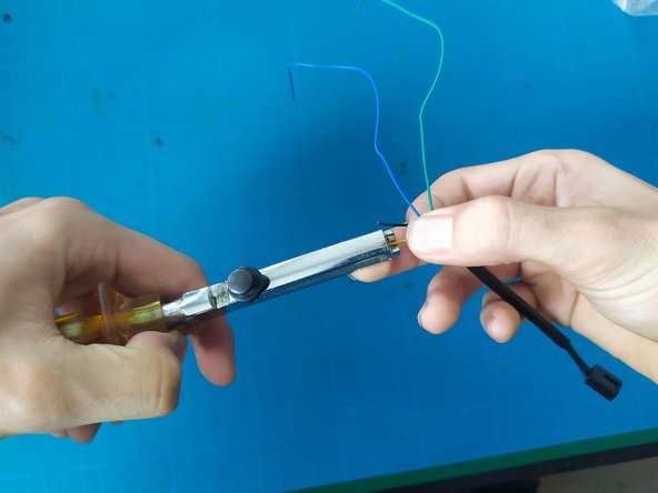
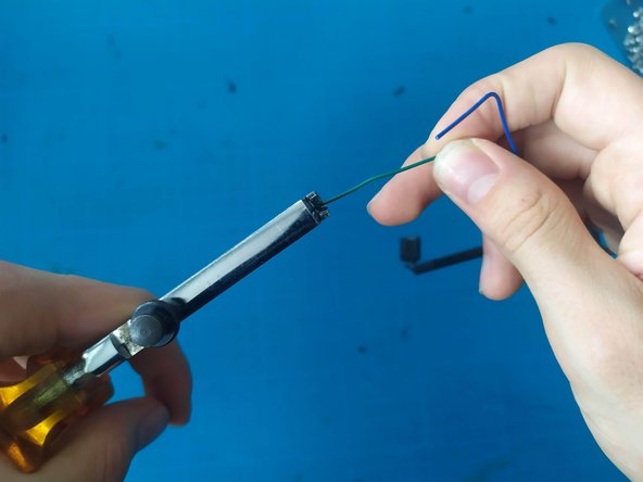
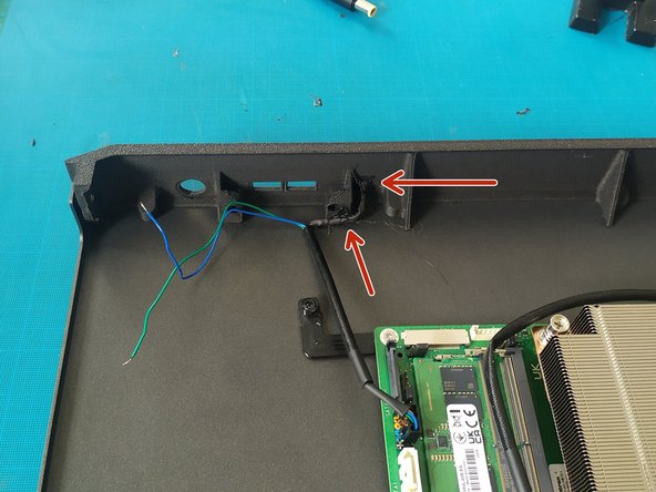
Strip, twist, and tin the green and blue wires.
-
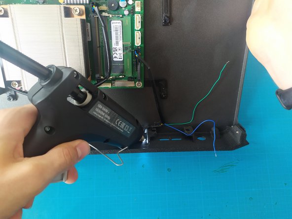
Glue the LED in place with the hot glue gun.
-
Gluing the LED while the motherboard is plugged in and/or turned on makes the task a bit easier.
-
-
-
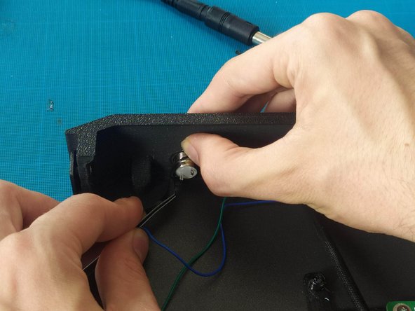
Install the button if you haven't already. With the seal on the inside.
-
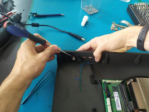
Screw on the nut and tighten it with a flathead screwdriver.
-
Slide a piece of heat shrink tubing onto each wire (green and blue).
-
-
-
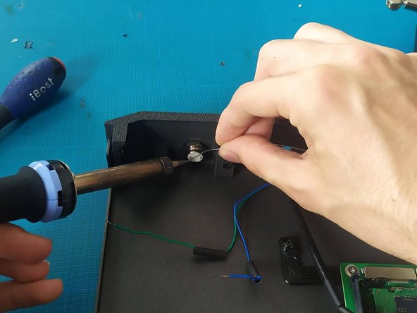
Tin the terminals of the button.
-
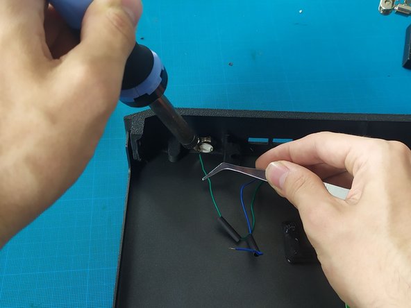
Solder the wires (no polarity).
-
Heat the heat shrink tubing with the heat gun.
-
-
-
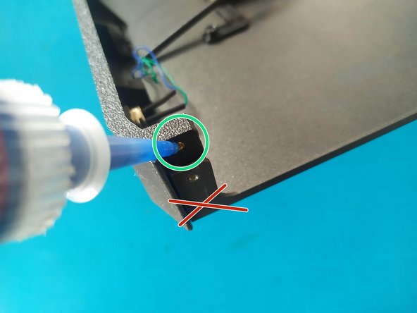
Add a drop of threadlocker into the top holes.
-
No threadlocker in the bottom holes.
-
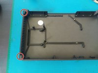
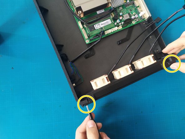
Drive 2 M2x5 Phillips screws from the outside.
-
Drive 2 M3x6 Torx screws from the inside (bottom holes).
-
-
-
Insert a USB extension.
-
Be careful to have the "bars" of the extension facing upwards (see photo).
-
Secure the connector with 2 Phillips screws.
-
-
-
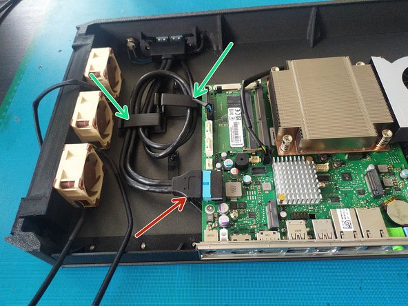
Connect the elbow connector.
-
Stick 2 large cable clips as shown in the photo.
-
Route the cable through the cable clips.
-
Plug the extension into the elbow connector.
-
-
-
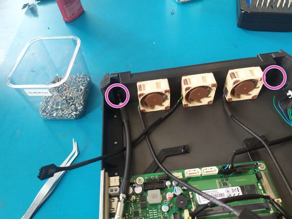
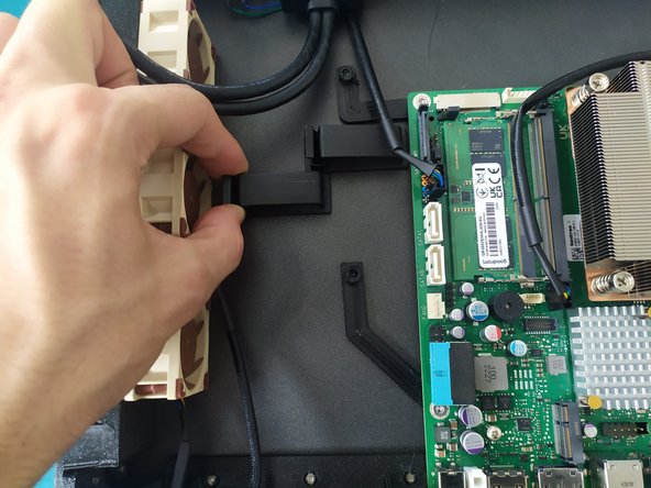
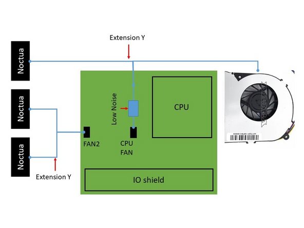
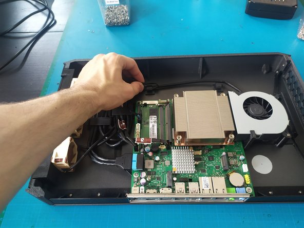
Connect the various cooling fans (see schematics).
-
Hook the various cables into the cable clips.
-
-
-
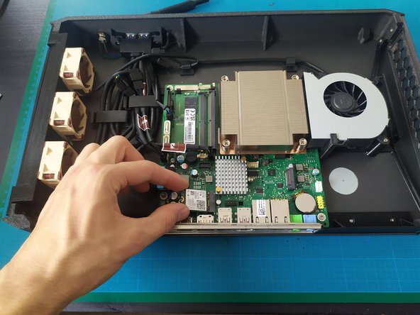
Install the Wi-Fi card.
-
Use the original screw to secure the Wi-Fi card.
-
-
-
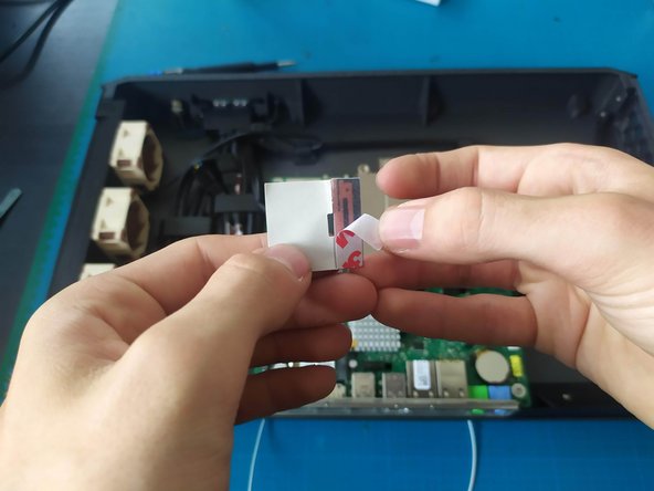
Remove the adhesive film from the antennas.
-
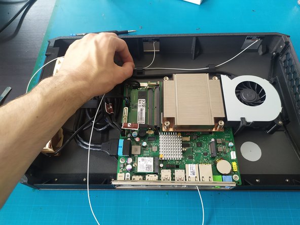
Stick the antennas down, placing them as far apart as possible.
-
Route the wires through the cable guides.
-
Connect the antennas.
-
-
-
Remove the SSD screw.
-
Install the SSD.
-
Drive the original screw into the SSD adapter.
-
-
-
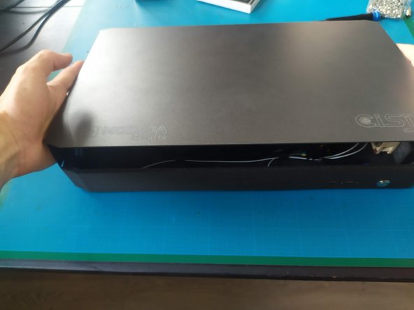
Add the top metal plate.
-
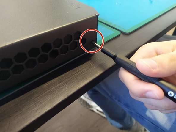
Secure the 4 black M3x6 Phillips screws (do not do this if parts are missing).
-
-