crwdns2933423:0crwdne2933423:0

Hyperkin Retron 3 Power Switch Replacement

crwdns2942213:0crwdne2942213:0

  1. Hyperkin Retron 3 Power Switch Replacement, Remove 6 screws loacted on the bottom of the system: crwdns2935265:01crwdnd2935265:01crwdnd2935265:01crwdne2935265:0
    • First and foremost, be sure to unplug both power and AV/S-Video cables and remove any games that may be plugged into the console.

    • In order to get into the system you're going to have to remove the 4 rubber boots on the bottom of the console in order to access 4 hidden screws underneath. The other two screws are already accessible.

    • These rubber boots are cheap and not easily reusable if they become stuck to each other or other items. I completely removed mine and because they weren't reattached right away they became stuck to each other and trying to pull them apart causes them to rip. In my case, I'm not particularly concerned if they are there or not and replacements

    • shouldn't be hard to find online I'd imagine.

    • If you'd like to avoid removing the boots utilize the picture provided to simply poke your screw driver threw the boot where the screw would be located. It might be tricky as you're looking for the only circle surrounded by several squares.

  2. Hyperkin Retron 3 Power Switch Replacement, Lift top half of system shell: crwdns2935265:02crwdnd2935265:01crwdnd2935265:02crwdne2935265:0 Hyperkin Retron 3 Power Switch Replacement, Lift top half of system shell: crwdns2935265:02crwdnd2935265:02crwdnd2935265:02crwdne2935265:0
    • DO NOT ATTEMPT TO COMPLETELY SEPARATE THE TWO HALVES AS THEY ARE CONNECTED VIA THE SYSTEM SWITCH DIAL ON THE UPPER SHELL AND THE MAIN PCB.

    • The cables have been glued down at the connection points as well. The upper shell and PCB unit don't need to be completely separated in order to get in and repair the system although it would make it easier.

    • Unless you are confident in removing this glue without causing damage and your soldering skills I don't advise trying to separate the two.

  3. Hyperkin Retron 3 Power Switch Replacement, Remove screws securing the PCBs to lower shell: crwdns2935265:03crwdnd2935265:01crwdnd2935265:01crwdne2935265:0
    • I find it easiest to prop up the top shell on the front right corner of the system. If you're using a flat surface it can stand by itself and there's enough slack in the Genesis PCB and Dial Switch cables to allow it to be positioned in such a way.

    • You can barely see it but the upper shell is standing upright on the front right corner.

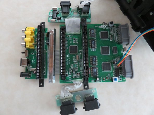
    • There are 11 screws that need to be removed in order to remove the entire PCB unit.

    • If the IR lens cover pops out at this point don't worry about it. It can be easily reinstalled during the reassembly process.

  4. Hyperkin Retron 3 Power Switch Replacement, Remove PCBs from lower shell: crwdns2935265:04crwdnd2935265:01crwdnd2935265:02crwdne2935265:0 Hyperkin Retron 3 Power Switch Replacement, Remove PCBs from lower shell: crwdns2935265:04crwdnd2935265:02crwdnd2935265:02crwdne2935265:0
    • The top shell won't be far away during this repair. Find a few objects to keep it upright or out of your way.

    • The AV/Power/NES PCB will be the last to remove during disassembly and first to replace during reassembly.

  5. Hyperkin Retron 3 Power Switch Replacement, Arrangment and Removal: crwdns2935265:05crwdnd2935265:01crwdnd2935265:02crwdne2935265:0 Hyperkin Retron 3 Power Switch Replacement, Arrangment and Removal: crwdns2935265:05crwdnd2935265:02crwdnd2935265:02crwdne2935265:0
    • As stated in the disassembly guide it's easiest to rest the upper shell on the front right corner of the system due to cable length restriction. The same will hold true here. I found it easiest to lift the main PCB at a 90 degree angle resting against the upper shell. Mind you the main PCB will be resting on the Genesis controller port PCB

    • Try to stabilize the NES controller board so that the cables don't become disconnected. If they do, you'll have to fight through the glue in order to resolder the cable.

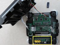
    • NES controller boards location.

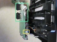
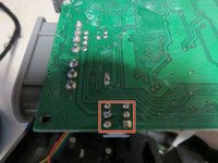
    • This is where your defective switch and it's 6 pins would be located looking at it from a downward angle.

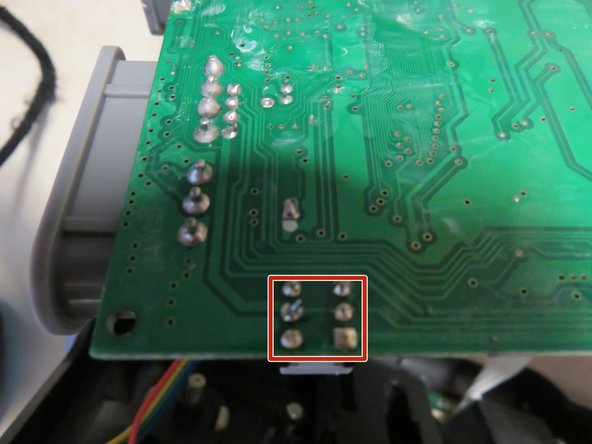
    • Once you've got the PCBs arranged in a way where they won't fall over you can begin to remove the switch. Either using a braid/pump/bridge the 6 pins that are soldered to the through holes of the main PCB and remove your defective on/off switch.

    • Mine has already been replaced so pictures will not depict what the board looks like without the switch.

  6. Hyperkin Retron 3 Power Switch Replacement, Cleanup and Replacement: crwdns2935265:06crwdnd2935265:01crwdnd2935265:01crwdne2935265:0
    • Be sure to clean up any residual solder or flux, if used, and clean the area with a Q-tip and rubbing alcohol or PCB cleaner to clean up the mess.

    • You will notice that the PCB itself looks kind of nasty. When I did this repair I cleaned the entire system inside and out. No matter how much I rubbed a Q-tip with PCB cleaner on it those white looking scuff marks still wouldn't come off. Don't be surprised if this happens to you. Better yet, don't waste your time :)

    • Once the mess, if present, is cleaned you can insert your replacement 8mmx8mm switch and solder the pins to the underside of the main PCB.

    • Once the soldering is complete then so is this repair. Simply reassemble your device and hit your power button and it should power up as if there was never a problem. If you can't keep the original consoles alive at least continue the great memories of your favorite 8-bit games. Happy Retro Gaming!

crwdns2915888:0crwdne2915888:0

To reassemble your device, follow these instructions in reverse order.

crwdns2935227:0crwdne2935227:0

Navy Vet 2015

crwdns2935283:006/25/15crwdne2935283:0

7,296 crwdns2915208:0crwdne2915208:0

crwdns2935297:015crwdne2935297:0

crwdns2944067:00crwdne2944067:0

crwdns2917038:0crwdne2917038:0

crwdns2936625:0crwdne2936625:0:

crwdns2936751:024crwdne2936751:0 0

crwdns2936753:07crwdne2936753:0 3

crwdns2936753:030crwdne2936753:0 12

crwdns2942667:0crwdne2942667:0 1,892