crwdns2942213:0crwdne2942213:0
-
-
Attempt to turn on the projection light and if it doesn't turn on then look through the hole where the projection comes out. If you can see a tiny clock image through the glass, then the problem is a burned out LED.
-
-
-
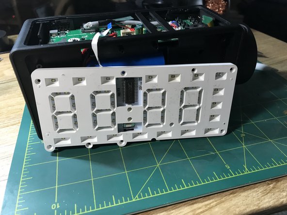
Using a sharp knife, get behind the reflective glass-like face from a corner, and remove the face from front of the clock. This may come off in one layer or two. Layer one is the reflective layer and layer two is a blackout layer to keep the time LEDs from bleeding light into other areas. Be sure you have both layers removed to see white plastic
-
-
-
Insert a flat-nose screw driver into the sides of the charge cover and begin to snap the charge cover off the top of the clock.
-
-
-
There are two screws holding down the wireless charging coil. I find this coil doesn't work well, so I snipped the positive and negative wires and desoldered the wire bits from the board to remove any opportunity for shorting.
-
-
-
This tiny flat cable is wedged into a connector on the circuit board. Pull it out carefully to avoid wrecking the cable, and remove the screws from the white plastic housing that holds the clock face LEDs.
-
-
-
Desolder the positive and negative power wires and wrap the ends with electrical tape to avoid harming the battery or any other parts.
-
-
-
Gently use the flat head screw drive to wedge into the side of the battery (avoid either end of the battery) and pry out the battery from the dark plastic. It is affixed using double-sided tape. Leave the tape on the battery. It can be reused to attach the battery later during re-assembly.
-
-
-
Remove the screws that attach the front-facing dark plastic housing from the clock. This will remove half of the inside of the clock. This holds the speakers as well as the projector wheel in place.
-
-
-
-
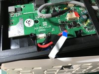
On top of the circuit board, find the cable with yellow, green, black, and gray wires. Carefully unplug the fixture that connects it to the board. You should be able to carefully push this cable out from it's position on the top of the board so it is inside the clock and connected to the projection wheel.
-
-
-
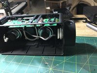
Carefully ensure the projector cable isn't wedged into any area under the circuit board or around the remaining base plastic housing. Grab the projection wheel and pull it toward the front and notice how it unseats from the plastic housing of the clock.
-
-
-
Remove the two screws holding the white plastic to the dark plastic.
-
-
-
Carefully pull the white plastic from the dark plastic and disassemble the projection wheel into five parts.
-
-
-
Remove the two screws from the projector circuit board. Wiggle the plastic house a tiny bit away from the circuit board. This will allow the tiny clock display screen to fall away from the plastic housing and circuit board. Make note the direction of the display that is wedged between the circuit board and the plastic housing.
-
-
-
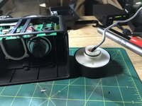
Dig out the soft rubber from the housing that holds the LED. With one of the screw drivers, push the LED through the dark plastic housing through the rubber to reveal the LED. Desolder the LED positive and negative wires from the board.
-
-
-
Measure the bend in the original LED positive and negative wires (the longer LED wire is the positive wire). Bend your new LED to match and perform a test fit from the circuit board and the plastic housing, to ensure the LED fits back into the housing with the correct bend angles. Solder the new LED into place.
-
-
-
At the bottom of the LED where the wires exit the dark plastic housing, push some versimold into the gap. You do not have to warm the mold to harden. Heat from the wires will affix it later. Be sure to pack enough to block any LED light leaks.
-
-
-
Place the tiny screen into the dark plastic housing that attaches to the projection circuit board with the bump in the screen facing out. Tighten the two screws back down to attached the circuit board, the dark housing as well as the screen.
-
-
-
Place the white octagonal piece above the tiny screen. There are three tiny nibs that align to show you how the small white plastic piece fits into place. Hold the circuit board with the white plastic piece balanced upward and align the lens over the plastic piece to hold it in place.
-
-
-
With the lens over the tiny screen place the screen and lens back into the large white plastic wheel half. The Circuit board will align tightly into plastic edges to hold it in place and the lens will just fit into the white plastic edges in the wheel half as well. You may have to rotate the lens to get the right side to fit.
-
-
-
Press the dark half carefully down into the white half until it fits appropriately. Flip the assembly over and put the two screws back in the white half.
-
-
-
Do the order of assembly in reverse, placing the gray projector cable up and under the clock circuit board and up to the top view of the clock and reconnect to the circuit board. Put the large dark housing of the face back in place with the projection wheel in place and put the screws back. Place the battery in the dark face housing and re-solder
-
-
-
Re attach the white face LED housing and replace screws. Place the LED tempalte and reflective face back in place. Fit the LED data strip back into the clock circuit board. You may need to wedge electrical tape into the top of the data strip cable to hold it in place. Power up the clock. If you do not see the clock face, press down on the data cabl
-
-
-
Once you have ensured the clock face data cable is wedge down on the lower connector wires and displays correctly, snap the top charge cover back in place. Test the new LED by pressing the projector button on the top of the clock.
-


To reassemble your device, follow these instructions in reverse order.
To reassemble your device, follow these instructions in reverse order.