crwdns2915892:0crwdne2915892:0
An Audio/Visual port enables a device to send or receive sounds and images. If these are not coming through, the A/V port may be at fault. If the A/V port is determined to be faulty, this guide will demonstrate how to replace the A/V port in the Konica Minolta DiMAGE Z3. This repair is not only relatively expeditious, but also relatively easy, and requires no major technical skills to complete.
crwdns2942213:0crwdne2942213:0
-
-
Open the battery chamber door by sliding the door to the side of the camera to release the safety catch.
-
Lift the door up to open.
-
-
-
Insert the four batteries inside of the battery chamber door.
-
Make sure the positive and negative battery terminals are in the correct position.
-
-
-
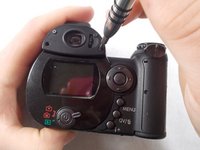
Use a screwdriver to remove the four viewfinder cover screws.
-
-
-
Remove the 2 small screws under the viewfinder.
-
-
-
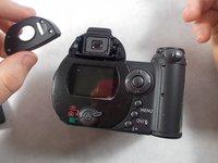
Remove the screen cover by applying slight pressure at the top, then pulling the screen protector away from the camera.
-
-
-
-
Remove 6 screws on the bottom panel.
-
-
-
Remove 1 screw on the outer side of the battery chamber.
-
-
-
Remove 1 screw inside the battery chamber.
-
-
-
Pull the wrist strap away from the front of the camera to remove it.
-
Then carefully pull the back casing apart from the camera.
-
-
-
Remove the 3 screws that attach the LCD screen to the circuit board.
-
-
-
Gently remove the LCD screen from the circuit board.
-
-
crwdns2935267:0crwdne2935267:0Tweezers$4.99
-
Use tweezers to carefully pull the ribbon cable from the circuit board, not from the LCD screen.
-
Peel back tape on LCD screen to reveal where the wires are attached. Use tweezers to detach the wires from the LCD screen.
-
-
-
Remove the single screw that connects the circuit board to the motherboard.
-
-
-
Carefully remove the circuit board from the motherboard.
-
Leave the wires attached to the circuit board.
-
-
-
The A/V port is glued to the motherboard. Heat should be applied carefully with a heat gun to loosen the adhesive.
-
Remove the A/V port with a spudger.
-


To reassemble the device, follow these instructions in reverse order.
crwdns2935221:0crwdne2935221:0
crwdns2935229:02crwdne2935229:0
crwdns2935287:0crwdne2935287:0

UMass Dartmouth, Team S7-G4, Julie Spring 2017 crwdns2935289:0UMass Dartmouth, Team S7-G4, Julie Spring 2017crwdne2935289:0
UMASSD-JULIE-S17S7G4
crwdns2931471:04crwdne2931471:0
crwdns2935297:08crwdne2935297:0
crwdns2947410:01crwdne2947410:0
Thanks for the help that enabled me to disassembling a Z5.
Is not exactly the same, but helped a lot.
I post comments about the differences I found.
I want only to reack the cursor buttons.
Regards
Joaquim