crwdns2915892:0crwdne2915892:0
This guide shows how to remove and replace the oil level switch for the Honda EU2200IT generator. The switch is attached from within the crankcase and requires major disassembly.
If you encounter problems during the process, consult the official Honda service guides.
Drain the fuel from the fuel tank before you begin this procedure. Any fuel remaining in the tank will spill out. Be ready to contain any spillage.
The crankcase must be resealed with liquid sealant. Be sure to have Threebond 1207B or equivalent liquid sealant at hand before you begin the procedure.
You will need to refill the engine oil for this procedure. The generator requires up to 0.46 liters of SAE 10W-30 oil.
You may find it helpful to loosely replace the bolts after you removed a part, in order to keep track of the bolts and to keep the screw holes clean.
crwdns2942213:0crwdne2942213:0
-
-
Lift and remove the spark plug cover.
-
-
-
Grab the plastic housing at the end of the spark plug wire.
-
Pull firmly to disconnect the wire from the spark plug.
-
-
-
Use a Phillips #2 screwdriver to loosen the screw holding the maintenance cover in place.
-
-
-
Swing the top of the maintenance cover out.
-
Remove the maintenance cover.
-
-
-
Unscrew and remove the oil filler cap.
-
-
-
Place an oil pan below the fill port to catch the engine oil.
-
Carefully tilt the generator towards the oil pan to drain the oil.
-
-
-
Add oil until the dipstick is almost completely submerged.
-
-
-
Place a container below the drain tube to catch the excess fuel.
-
-
-
The carburetor drain screw is located at the bottom of the carburetor.
-
Use a flathead screwdriver to loosen the fuel drain screw until fuel begins to drain out of the carburetor.
-
Once you drain the fuel bowl, re-tighten the fuel drain screw.
-
-
-
Remove the four Phillips screws securing the back cover.
-
-
-
Remove the four screws securing the front cover:
-
Two Phillips screws
-
Two Phillips screws (one on each side)
-
-
-
Swing the top edge of the front cover away from the generator.
-
Pull the front cover away slightly away.
-
-
-
Remove the lower gray plates from both sides of the generator.
-
-
-
Remove the fasteners securing the left (non-access) cover:
-
Two Phillips screws
-
Two 10 mm bolts
-
-
-
Slide the vent and drain tubes out of their cover ports along the bottom of the right cover.
-
-
-
Remove the Phillips screw securing the starter rope port.
-
-
-
Thread the starter rope handle through the port's cutout.
-
-
-
Remove the right (access-side) cover.
-
-
-
Use a screwdriver to pry and loosen the diaphragm tube from the fuel pump.
-
Disconnect the diaphragm tube from the fuel pump.
-
-
-
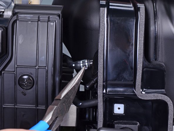
Use a pair of pliers to squeeze and slide the spring clip off the fuel pump port.
-
-
-
Disconnect the fuel hose from the fuel pump.
-
-
-
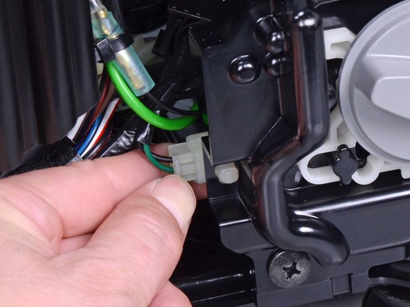
Pull and disconnect the engine stop switch connector from its socket.
-
-
-
-
Remove the Phillips screw securing the starter rope guide.
-
-
-
Feed the starter rope handle and guide through the panel cutout.
-
-
-
Use a pair of pliers to squeeze and slide the spring clip off the fuel tank port.
-
-
-
Disconnect the fuel line and filter from the fuel tank.
-
-
-
Remove the Phillips screw securing the left (non-access) frame assembly.
-
-
-
Remove the left (non-access) frame assembly.
-
-
-
Use a 10 mm socket to remove the three bolts securing the muffler:
-
Two 50 mm-long bolts
-
One 75 mm-long bolt
-
-
-
Use a wire brush to clean any deposits off the spark arrester.
-
-
-
Use a flathead screwdriver to pry up the blue wire harness from the under-cover.
-
-
-
Use a mallet and punch to tap out the front collar (closest to the electrical panel) securing the motor assembly to the under-cover.
-
-
-
Use a 10 mm socket to remove the two bolts securing the motor rear to the under-cover.
-
-
-
Lift the motor assembly off the under-cover and set it aside.
-
-
-
Use a 10 mm socket to remove the two bolts securing the left shroud.
-
-
-
Begin separating the left shroud from the engine assembly by pulling it away from the assembly.
-
-
-
Pull along the edge of the shroud until you separate the shroud from the engine assembly.
-
Remove the shroud.
-
-
-
Remove the Phillips screw securing the filter cover.
-
Remove the filter cover.
-
-
-
Remove the air filters from the filter box.
-
Clean the filters in warm soapy water
-
Allow the filters to dry thoroughly
-
Dip the filters in clean engine oil, and squeeze out excess oil
-
-
-
Disconnect the breather tube from the air cleaner housing.
-
-
-
Remove the following fasteners securing the housing:
-
Two 8 mm nuts
-
One 8 mm bolt
-
-
-
Unclip the fuel and air hoses from the side of the motor assembly.
-
-
-
Pull the breather tube straight out of its port.
-
-
-
Use a flathead screwdriver to unclip the carburetor wires from the side of the motor assembly.
-
-
-
Slide the carburetor off its two bolt rails.
-
-
-
Use an 8 mm socket to remove the two bolts securing the carburetor insulator.
-
-
-
Remove the carburetor insulator along with the two bolt rails.
-
-
-
Use a 10 mm socket to remove the bolts securing the right shroud.
-
-
-
Begin separating the right shroud from the engine assembly by pulling it away from the assembly.
-
-
-
Pull the shroud away along the edge. Use a flathead screwdriver to pry it out of the engine assembly groove.
-
-
-
Remove the right shroud from the engine assembly.
-
-
-
Use a 10 mm socket to remove the two bolts securing the exhaust pipe.
-
-
-
Remove the exhaust pipe from the engine assembly.
-
-
-
Loosen the cable tie securing the engine oil sensor.
-
-
-
Disconnect the yellow engine oil sensor wire by pulling the connector apart.
-
-
-
Use a 10 mm socket to remove the bolt securing the engine oil sensor ground.
-
-
-
Use a 10 mm socket to remove the eight bolts securing the crankcase cover.
-
-
-
Insert a large flathead screwdriver or pry bar into the crankcase seam and pry to loosen the crankcase cover.
-
Pry along the entire crankcase perimeter until you fully loosen the crankcase cover.
-
-
-
Separate and remove the crankcase cover.
-
-
-
Clean all adhesive and oil residue off of the cover and crankcase mating surfaces.
-
Apply a bead of liquid sealant to the crankcase.
-
Fit the crankcase cover to the crankcase.
-
-
-
Use a 10 mm socket to remove the bolt securing the oil level sensor.
-
-
-
Thread the sensor cable through the port and remove the sensor.
-
To reassemble your device, follow these instructions in reverse order.
To reassemble your device, follow these instructions in reverse order.
crwdns2935221:0crwdne2935221:0
crwdns2935227:0crwdne2935227:0


