crwdns2915892:0crwdne2915892:0
This guide shows how to remove and replace the rotor for the Honda 6500 Watt Generator EG6500CL AT.
Warning: You need a Honda rotor puller tool (07HPC-ZC2010A or 07HPC-ZC2010B) in order to complete this procedure. You will not be able to remove the rotor without this tool.
This procedure shows how to complete the procedure without removing the generator from the frame.
You will need some wooden blocks between 2-4 inches thick to support the generator and rotor. You will also need a metal rod or extra large screwdriver in order to brace and lock up the generator axle.
crwdns2942213:0crwdne2942213:0
-
-
Before you work on the device, make sure to switch the engine off.
-
Switch the circuit breaker off.
-
-
-
Grab the plastic housing at the end of the spark plug wire.
-
Pull firmly to disconnect the wire from the spark plug.
-
-
-
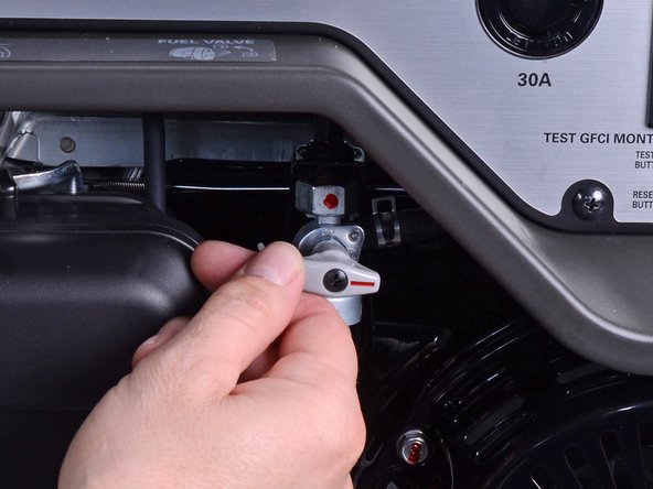
Twist the fuel valve clockwise into the cutoff position.
-
-
-
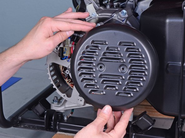
Use a Phillips screwdriver to remove the two screws securing the generator cover.
-
-
-
Squeeze and disconnect the stator connector from the wiring harness.
-
-
-
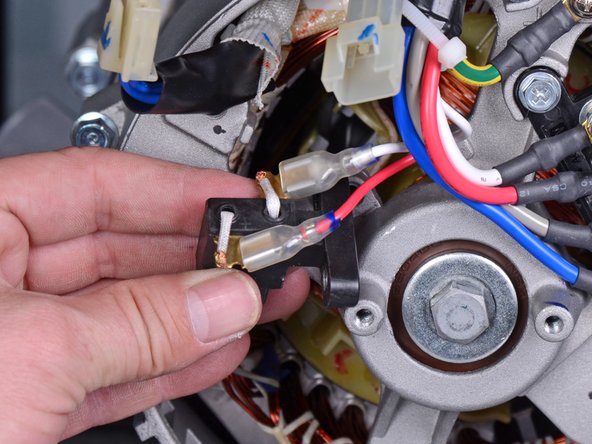
Use a 10 mm socket to remove the bolt securing the brush assembly.
-
Pull the brush assembly out slightly from its recess.
-
-
-
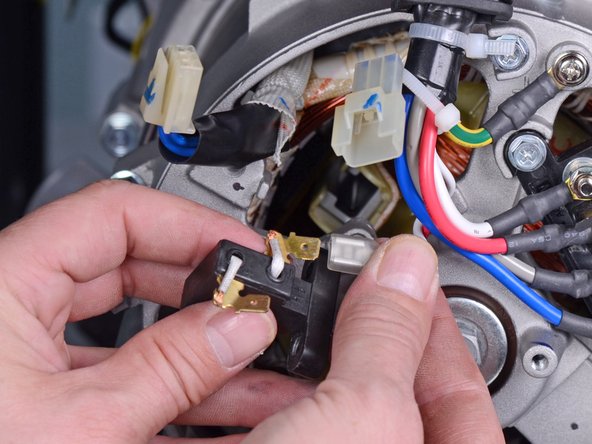
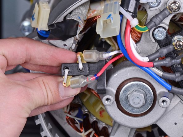
Disconnect the two spade connectors from the brush assembly.
-
-
-
Use a 10 mm socket to remove the four long bolts securing the generator cover to the generator assembly.
-
-
-
Use a 14 mm socket to remove the rotor bolt from the generator assembly.
-
-
-
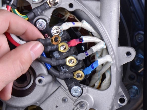
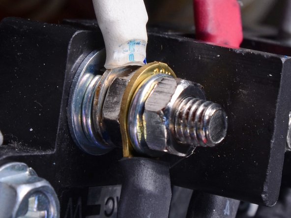
Use an 8 mm socket to remove the four nuts securing the wiring harness to the terminal.
-
Remove the wiring harness wires from the terminal.
-
-
-
-
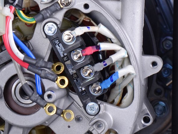
Base washer
-
Crush washer
-
Stator wire connector
-
Nut
-
Wiring harness connector
-
Crush washer
-
Nut
-
-
-
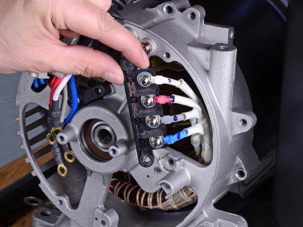
Use an 8 mm socket to remove the three bolts securing the wiring terminal and harness.
-
Remove the Phillips screw securing the harness ground.
-
Loosen the wiring terminal and harness from their resting positions.
-
-
-
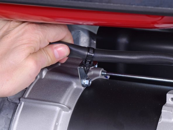
Use pliers to release the cable tie securing the wiring harness to the generator assembly.
-
-
-
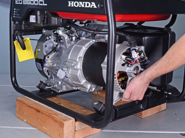
Carefully tilt the rear of the generator upwards to access the under-frame bolts.
-
Use a 12 mm socket to remove the two bolts underneath the frame, which secures the rear generator housing.
-
-
-
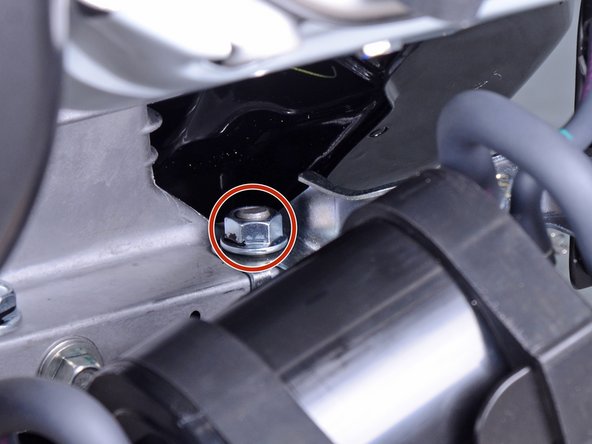
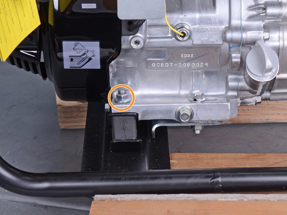
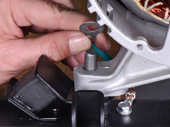
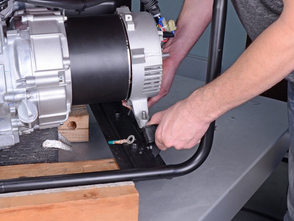
Use a 14 mm socket to remove the mounting nut next to the emissions canister.
-
Use a 14 mm socket to remove the mounting nut near the oil filler hole.
-
-
-
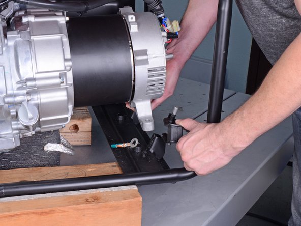
Use a 14 mm socket to remove the two nuts securing the rear housing to the bushings.
-
-
-
Tilt the generator assembly by lifting the rear housing slightly.
-
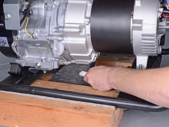
Place support blocks underneath the silver generator housing to support the generator assembly.
-
-
-
Lift the rear generator housing up as far as you can and maneuver the left bushing out of its socket.
-
Remove the left bushing.
-
-
-
Repeat the previous step to remove the right bushing from its socket.
-
-
-
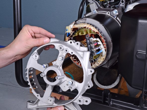
Remove the rear generator housing from the generator assembly.
-
-
-
Rotate the stator cover so that the seam is at an accessible angle.
-
-
-
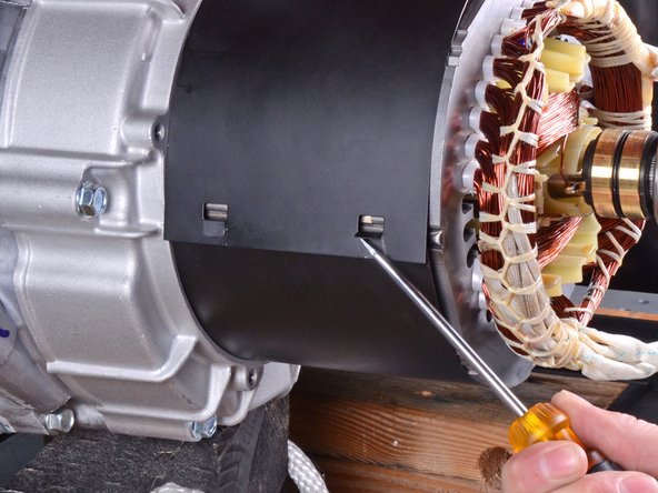
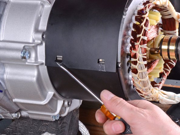
Use a flathead screwdriver to pry up the tabs holding the stator cover together.
-
-
-
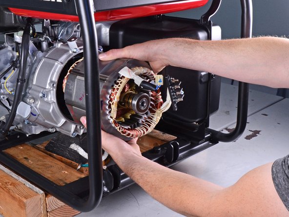
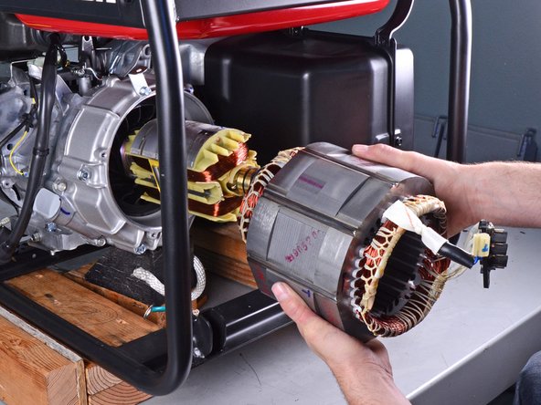
Remove the stator by pulling it straight out of the generator assembly.
-
-
-
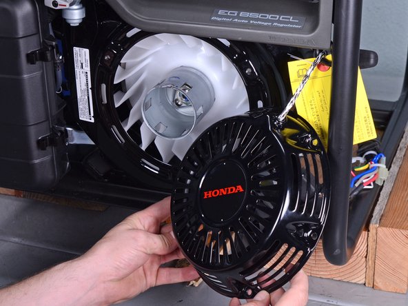
Use a 10 mm socket to remove the three bolts securing the recoil starter.
-
-
-
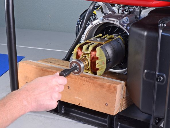
Place wooden blocks under the flat side of the rotor to prevent it from rotating.
-
-
-
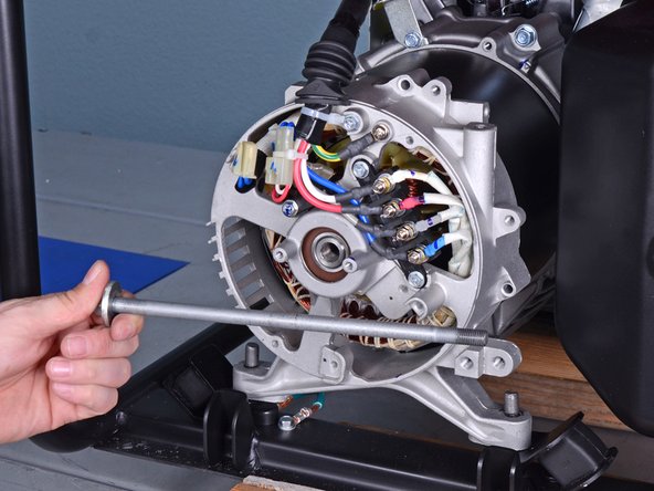
Insert a metal rod or a large screwdriver through the starter pulley to lock the rotor axle in place.
-
-
-
Insert the rotor puller tool into the rotor axle.
-
Hand-tighten the puller tool onto the rotor threads.
-
-
-
Use a 19 mm socket to tighten the puller tool until it breaks the rotor free from the generator assembly.
-
-
-
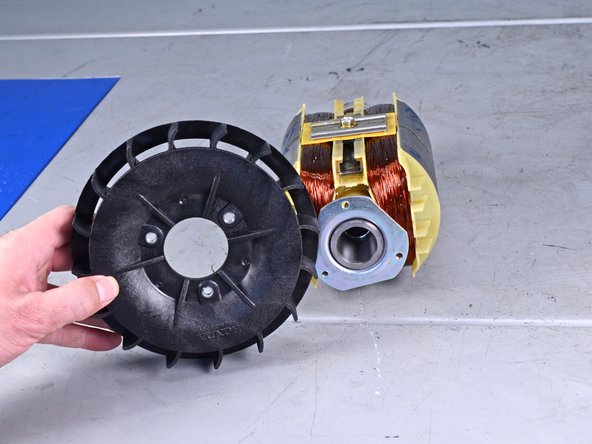
Use an 8 mm socket to remove the three bolts securing the rotor fan.
-
Transfer the fan to your replacement rotor.
-
-
-
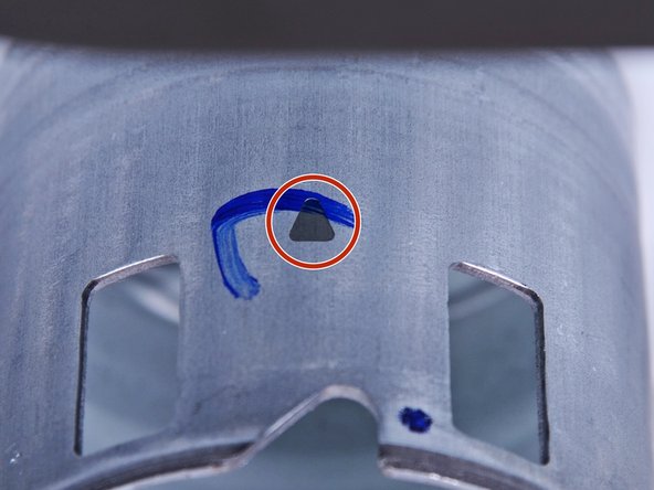
Rotate the starter pulley until the top-dead-center marker is facing straight up.
-
Once aligned, do not rotate the starter pulley or drive shaft until you've attached the rotor.
-
-
-
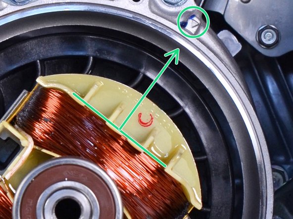
Align the rotor such that the flat side of a rotor coil sits perpendicular to the alignment arrow at the top-right edge of the generator case.
-
-
-
Insert the rotor bolt and washer into the rotor axle.
-
Use a 14 mm socket and torque wrench to tighten the rotor bolt to 33 ft-lb (44 N-m).
-
Reassemble the rest of the generator by following the instructions in reverse.
-


To reassemble your device, follow these instructions in reverse order.
To reassemble your device, follow these instructions in reverse order.
crwdns2935221:0crwdne2935221:0
crwdns2935227:0crwdne2935227:0

