crwdns2915892:0crwdne2915892:0
In this guide we will be showing you how to replace the RAM on your HP Pavilion x360 m3-u103dx. This will help if your computer starts to slow down or if you are just looking for an upgrade. The RAM is located on the underside of the motherboard when coming from a keyboard first entry.
crwdns2942213:0crwdne2942213:0
-
-
Shut down the computer.
-
Disconnect the power and all external devices connected to the computer.
-
-
-
Use a Metal Spudger and remove the rubber foot closet from the bottom of the laptop.
-
-
-
Remove all of the screws located on the bottom of the laptop:
-
5 Phillips 2.4 x 5.7 mm screws
-
5 Phillips 2.0 x 5.0 mm screws
-
-
-
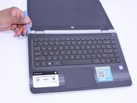
Turn the computer over onto its base, with the computer open and the keyboard facing upward.
-
-
-
Use the Plastic Opening Tool to separate the keyboard from the base of the laptop.
-
-
-
Raise the keyboard slightly to access the touch pad and keyboard cables.
-
-
crwdns2935267:0crwdne2935267:0Heavy-Duty Spudger$4.99
-
Disconnect the ribbon cables attaching the touch pad and keyboard to the system board (motherboard).
-
Using the Heavy-Duty Spudger lift up the plastic locks connecting the ribbon cable to the motherboard.
-
Use the blue plastic tab on the ribbon cable to pull it out from the lock on the motherboard.
-
-
-
-
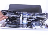
Lift the keyboard away from the base of the laptop.
-
-
-
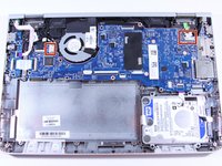
Using the Phillips 00 Screwdriver, remove 6 Phillips 2.0 x 4.6 mm screws from the perimeter of the battery.
-
-
-
(You don't NEED to remove this shielding as you can remove the board with it still there.)
-
Remove the adhesive strip.
-
Lift the shield away from the base of the laptop.
-
-
crwdns2935267:0crwdne2935267:0Heavy-Duty Spudger$4.99
-
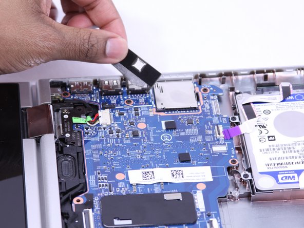
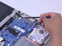
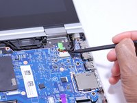
Disconnect the ribbon cables attached to the system board (motherboard).
-
Using the Heavy-Duty Spudger lift up the plastic locks connecting the ribbon cable to the motherboard.
-
Use the plastic tab on the ribbon cable to pull it out from the lock on the motherboard.
-
-
-
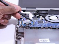
Disconnect the fastened cables from the system board (motherboard) by carefully pushing the cable's plastic edges using the Heavy Duty Spudger.
-
-
-
Pull the clipped cables from system board (motherboard).
-
-
-
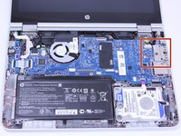
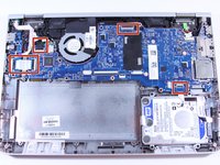
Remove the system board (motherboard).
-
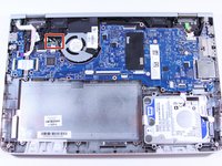
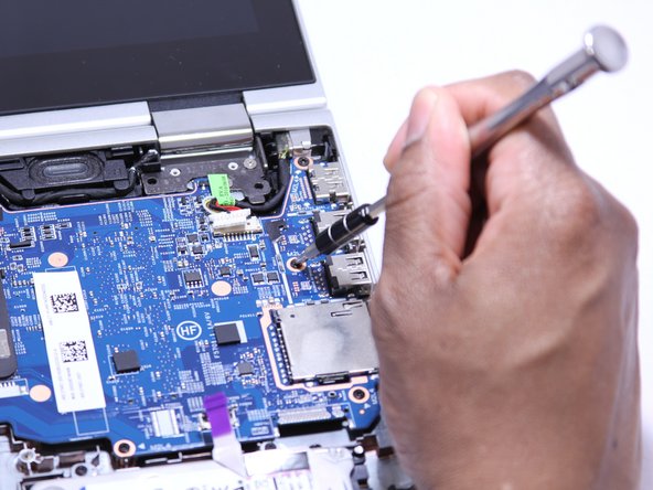
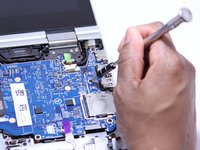
Using the Phillips 00 Screw Driver, remove 9 Phillips 2.0 x 4.7 mm screws with "M2L4" next to them.
-
Using the Phillips 00 Screw Driver, remove the silver screw.
-
-
-
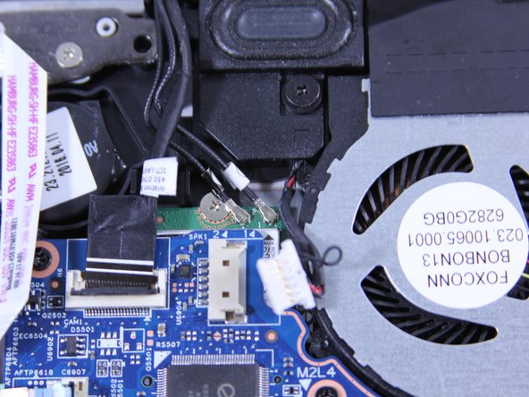
Using a Heavy Duty Spudger, disconnect the black and red RTC battery cable on the left side of the system board (motherboard).
-
-
-
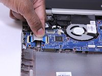
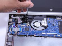
Release the system board (motherboard) from the base enclosure.
-
-
-
Gently pry off the metal container holding the RAM.
-
-
-
Push both tabs outward, so that the RAM pops up.
-
-
-
Gently lift the RAM out of the socket, retaining the 30 degree angle it rests at.
-


To reassemble your device, follow these instructions in reverse order.
To reassemble your device, follow these instructions in reverse order.
crwdns2915084:0crwdne2915084:0

IUPUI, Team S2-G2, Wilson Summer 2019 crwdns2935289:0IUPUI, Team S2-G2, Wilson Summer 2019crwdne2935289:0
IUPUI-WILSON-SU19S2G2
crwdns2931471:04crwdne2931471:0
crwdns2935297:02crwdne2935297:0