crwdns2942213:0crwdne2942213:0
-
-
Lay the computer face-down on a flat surface. Orient the computer to match the image.
-
Locate the battery release switch, as indicated in the image by the red rectangle. Slide the switch from right to left, and remove the battery.
-
-
-
Remove the two 5mm Phillips screws on the right side of the RAM cover.
-
Lift the right side of the RAM cover, and remove it.
-
-
-
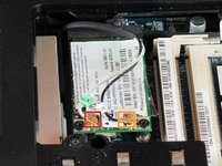
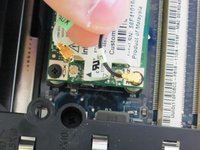
Disconnect the antenna leads from the wifi card by lifting the gold ends of the wires off the prongs on the wifi card.
-
The white wire connects to the AUX terminal.
-
The black wire connects to the MAIN terminal.
-
-
-
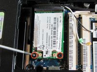
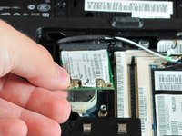
Remove the two 6.0mm Phillips screws from the wifi card.
-
Remove the wifi card.
-
-
-
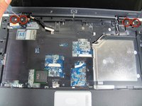
Remove the two 11.0mm screws at the corners on either side of the battery compartment.
-
Remove the three 6.0mm screws.
-
Remove the two 5.0mm screws.
-
Remove the 6.0mm screw in the middle of the battery compartment.
-
-
-
-
Turn the computer over and open the screen. This provides access to the screen hinges.
-
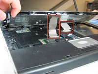
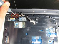
The keyboard switch cover is attached to the computer with a series of snaps. With a flathead screwdriver, pry up the switch cover until it pops free.
-
-
-
Be careful not to bend the keyboard switch cover too far when removing it.
-
-
-
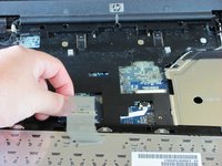
Next, remove the keyboard. Push on the keyboard frame above the function keys and slide the keyboard toward the screen.
-
-
-
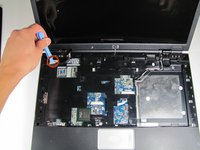
Carefully lift the trackpad-side edge of the keyboard to reveal the LED and keyboard cable connectors.
-
Detach the cable connectors from the computer by gripping each cable connector close to the computer contact point and pulling up gently.
-
-
-
Lay the keyboard face down.
-
Remove the four 3.00mm screws that attach the keyboard to the keyboard frame.
-
-
-
Lift the keyboard off the keyboard frame.
-
-
-
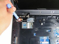
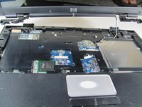
Use the plastic prying tool to disconnect the screen cable from the system board.
-
-
-
Remove the four 7.0mm screws securing the screen to the computer.
-
-
-
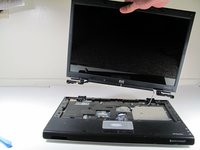
Separate the screen from the computer frame by lifting the screen straight up.
-
Disconnect the PCI wires by pulling them free of the computer.
-


To reassemble your device, follow these instructions in reverse order.
crwdns2935221:0crwdne2935221:0
crwdns2935229:03crwdne2935229:0
crwdns2935287:0crwdne2935287:0

Cal Poly, Team 21-34, Regan Fall 2010 crwdns2935289:0Cal Poly, Team 21-34, Regan Fall 2010crwdne2935289:0
CPSU-REGAN-F10S21G34
crwdns2931471:04crwdne2931471:0
crwdns2935297:011crwdne2935297:0
crwdns2947410:01crwdne2947410:0
To reinstall the PCI WIRES I'm finding no other way to reattach them except by removing the outer cover AND RE-ATTACHING. . I will finish-up the repair and send you my results