crwdns2915892:0crwdne2915892:0
Follow this guide to remove a faulty display in your HP Officejet Pro 8620. If the touch-screen display is unresponsive, has image burn in, or stuck pixels you will need to replace the display.
crwdns2942213:0crwdne2942213:0
-
-
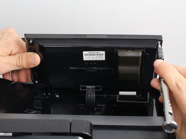
Place the printer on its back and rotate the display clockwise to gain access to the underside of the display.
-
-
-
Locate the control arm on the underside of the display. You will need to detach this to access the screws.
-
Place a finger behind the control arm.
-
Separate the display unit from the control arm by pulling down with your finger and using your other hand to push the display unit up.
-
-
-
-
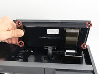
Remove the four 11mm T9-Torx screws on the underside of the display unit by rotating the screwdriver counter clockwise.
-
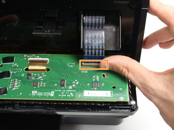
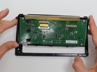
Open the display unit to expose the circuit board by separating the back and front panels.
-
Remove the ribbon cable by gently releasing the plastic locking mechanism and pulling the cable away from the circuit board.
-
-
-
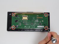
Remove the four 7mm T9-Torx screws from the circuit board that are holding the screen in place using a T9-Torx screwdriver and turning counter clockwise.
-
Lift the circuit board/screen panel from the black frame.
-


To reassemble your device, follow these instructions in reverse order.
crwdns2935221:0crwdne2935221:0
crwdns2935229:04crwdne2935229:0
crwdns2935287:0crwdne2935287:0

Cal Poly, Team S19-G2, Livingston Winter 2018 crwdns2935289:0Cal Poly, Team S19-G2, Livingston Winter 2018crwdne2935289:0
CPSU-LIVINGSTON-W18S19G2
crwdns2931471:03crwdne2931471:0
crwdns2935297:08crwdne2935297:0