crwdns2915892:0crwdne2915892:0
Replace the USB and Power board in your HP Mini 1000.
crwdns2942213:0crwdne2942213:0
-
-
With the case closed, place the Mini 1000 top-side down on a flat surface.
-
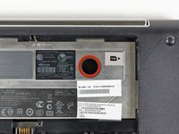
Push both of the battery release latches toward each other.
-
-
-
Lift the battery out of the Mini 1000 from the edge closest to the release latches.
-
-
-
Remove the following two screws:
-
One 6 mm Phillips screw
-
One 4 mm Phillips screw
-
-
-
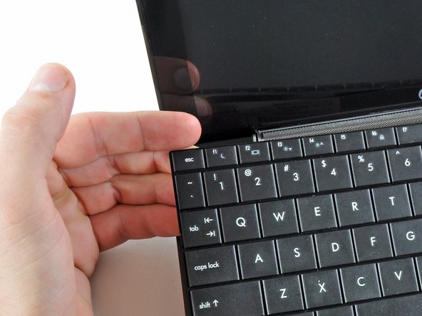
While pushing through the opening with one hand, grasp the left upper edge with the other hand and slightly pull the keyboard towards you.
-
Once an opening has been established, grasp the keyboard and slowly lift it upwards along the upper perimeter of the top edge.
-
-
-
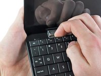
Lift the keyboard out of the upper case, minding the cable that is still connecting it to the motherboard.
-
-
-
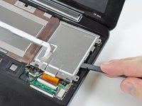
Use your fingernail or the flat end of a spudger to flip up the retaining flap on the keyboard cable ZIF socket.
-
Pull the cable out of its socket and remove the keyboard.
-
-
-
Use your fingernail or the flat end of a spudger to flip up the retaining flap on the SIM card ribbon cable ZIF socket.
-
Pull the SIM card ribbon cable out of its socket and peel it off the top of the hard drive enclosure.
-
-
-
Use your fingernail or the flat end of a spudger to flip up the retaining flap on the hard drive cable ZIF socket.
-
-
-
Remove the two 4.5 mm Phillips screws securing the hard drive to the lower case.
-
-
-
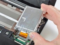
Lift the hard drive up and out of the lower case, being careful not to damage its cable in the process.
-
-
-
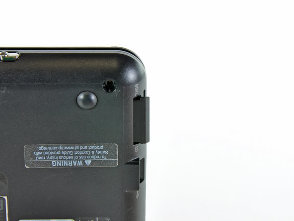
Using the sharp tip of a spudger, pry and remove the four plastic screw covers from the underside of the HP Mini 1000.
-
The two bottom covers are short in height and are notched to prevent incorrect insertion
-
The upper right cover is taller in height and is notched.
-
The upper left cover is taller in height and is not notched.
-
-
-
Remove the four 7 mm Phillips screws that secure the upper case to the lower case.
-
-
-
Flip the computer over and open the display.
-
Remove the two 4.5 mm Phillips screws securing the upper case to the lower case.
-
-
-
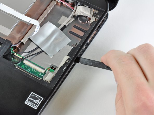
Wedge the flat end of a spudger in between the upper case and lower case near the bottom right corner of the display.
-
Carefully pry and rock the spudger upwards to create a small gap between the upper case and lower case.
-
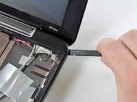
Continue the previously described motion along the right edge of the upper case to release the clips securing the upper case to the lower case.
-
-
-
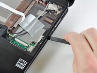
Repeat the same procedure as mentioned in the previous step to release the clips along the left side of the upper case.
-
-
-
Grasp the upper case and carefully lift it slightly upwards, freeing it from any remaining clips.
-
-
-
Use your fingernail or the flat end of a spudger to flip up the retaining flap on the TouchPad cable ZIF socket.
-
Pull the TouchPad ribbon cable out of its socket.
-
Remove the upper case from the HP Mini 1000.
-
-
-
-
Push the SD card toward the inside of the computer to unlock it from the lower case.
-
Pull the SD card out of the lower case.
-
-
-
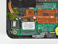
Pry the Wi-Fi antenna connectors (2 total) up off the Wi-Fi board.
-
-
-
Remove the single 3 mm Phillips screw securing Wi-Fi board to the motherboard.
-
-
-
Grasp the Wi-Fi board and lift it straight away from its socket on the motherboard.
-
-
-
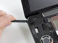
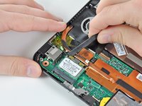
Remove the two 2.5 mm Phillips screws securing the heat sink to the motherboard.
A magnetic Philips #0 makes this much easier to reassemble than non-magnetic.
-
-
-
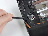
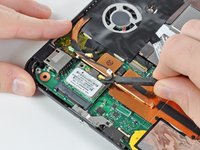
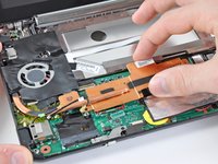
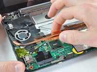
Carefully lift the heat sink off the face of the motherboard and de-route the curved section from next to the fan.
-
Before reinstalling the heat sink, be sure to apply a new layer of thermal paste to the CPU. We have a thermal paste guide that makes it easy.
This reassembly needs to precede the installation of the the plastic that covers the fan.
-
-
-
Pry the WWAN antenna connectors (2 total) up off the WWAN board.
-
-
-
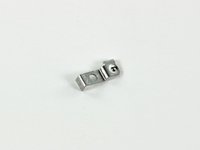
Remove the single 3 mm Phillips screw securing the WWAN metal bracket and WWAN board to the motherboard.
-
-
-
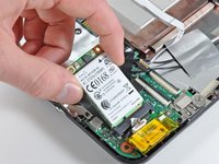
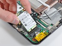
Grasp the WWAN board and pull it straight out of its socket on the motherboard.
-
-
-
Use the flat end of a spudger to lift the Bluetooth cable connector out of its socket on the motherboard.
-
Carefully pry the Bluetooth board off the motherboard and remove it from the Mini 1000.
-
-
crwdns2935267:0crwdne2935267:0Tweezers$4.99
-
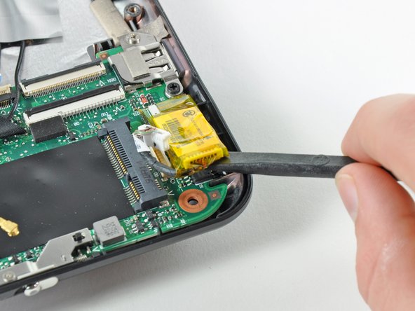
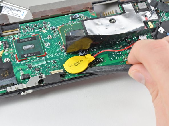
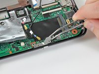
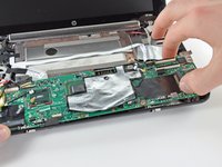
Use a pair of tweezers to pull the PRAM battery connector out of its socket on the motherboard.
-
Use the flat end of a spudger to pry the PRAM battery off the adhesive securing it to the motherboard.
-
Remove the PRAM battery.
-
-
Prepare steps 24-22 on reinstallation, so you know where to line up the tape. These steps go somewhat together on reassembly.
-
-
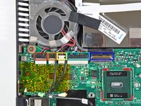
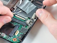
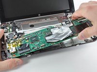
Use the flat end of a spudger or your fingers to disconnect the following cables:
-
Speaker cable
-
Microphone cable
-
Fan cable
-
Power cable
-
Display data cable
-
-
crwdns2935267:0crwdne2935267:0Tweezers$4.99
-
Remove the 2.5 mm Phillips screw securing the power switch lever to the lower case.
-
Use a pair of tweezers or your fingers to lift the power switch lever out of the Mini 1000.
Bend the levers in step 35+36 slightly before reassembly, so that the screws push them down tighter. The levers appear to slacken with age.
-
-
-
Remove the 2.5 mm Phillips screw securing the wireless on/off switch lever to the lower case.
-
Use tweezers or your fingers to remove the wireless on/off switch lever from the Mini 1000.
-
-
-
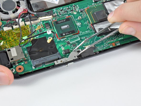
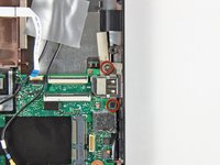
Remove the two 3 mm Phillips screws securing the USB bracket to the lower case.
-
Pry up the USB bracket and remove it from the motherboard.
-
-
-
Remove the single 4.5 mm Phillips screw securing the motherboard to the lower case near the fan.
-
-
-
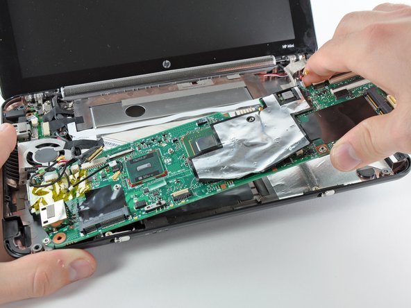
Carefully lift the motherboard from its right edge and remove it from the lower case, minding any cables that may get caught.
When reinstalling, insert left side first, slightly pry right side of case to get motherboard to seat.
There's another four wire connector on the back of the board on the right, connected to an unused item that appears to be USB (but that would have five wires, right?)
-
-
-
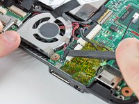
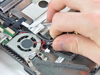
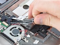
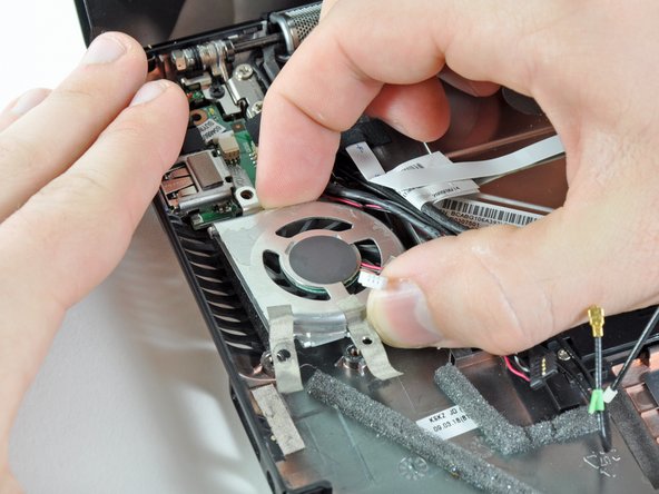
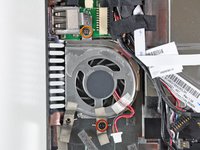
Carefully untangle the fan cable from the bundle of cables leading to the display.
-
-
-
Remove the following two screws:
-
One 3 mm Phillips screw
-
One 4.5 mm Phillips screw
-
Remove the fan from the lower case.
-
-
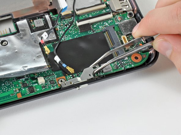
crwdns2935267:0crwdne2935267:0Tweezers$4.99
-
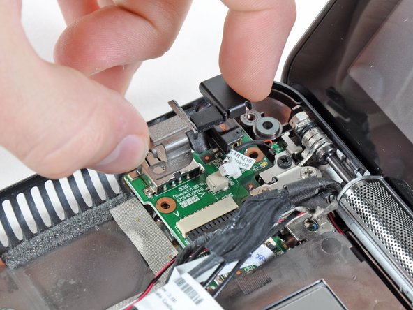
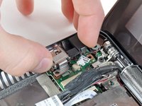
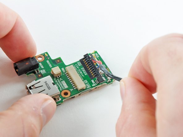
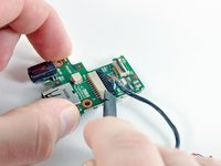
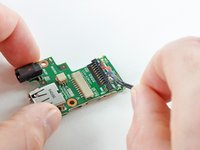
Use a pair of tweezers to pull the internal display switch cable straight away from its socket on the USB and power board.
-
-
-
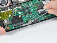
Peel and de-route the SIM card ribbon cable from its channel on top of the underside of the battery compartment.
-
-
-
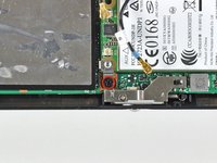
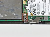
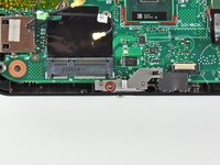
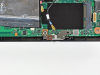
Remove the single 3 mm Phillips screw that secures the USB and power board as well as the DC jack bracket to the lower case.
-
-
-
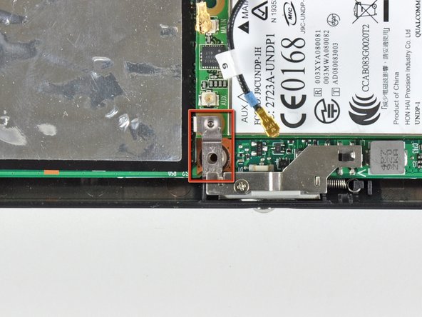
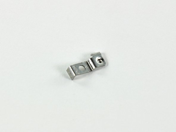
Lift the DC jack bracket up off the USB and power board.
-
-
-
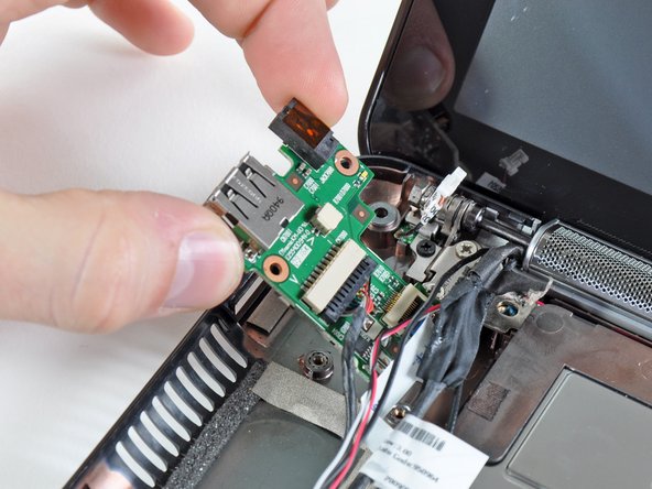
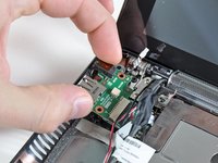
Grasp the USB and power board from its left edge, nearest the ports side.
-
Remove the USB and power board straight away from its recess in the lower case, minding any cables that may get tangled.
-
-
-
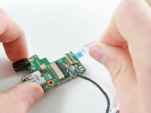
Use your fingernail or the flat end of a spudger to flip up the retaining flap on the SIM card cable ZIF socket.
-
Pull the SIM card ribbon cable out of its socket.
-
-
-
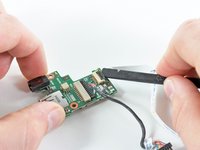
Use the flat end of a spudger to gently push the power cable from its socket.
-
Pull the power ribbon cable out of its socket.
-


To reassemble your device, follow these instructions in reverse order.
To reassemble your device, follow these instructions in reverse order.

crwdns2947410:01crwdne2947410:0
Where to find this replacement board?