crwdns2915892:0crwdne2915892:0
Use this guide to replace the broken display on your HP Envy Ultrabook 4-1015dx.
crwdns2942213:0crwdne2942213:0
-
-
Make sure that the device is turned off and that all external devices are removed.
-
-
-
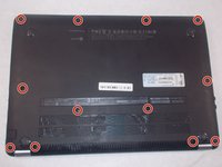
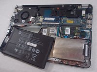
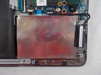
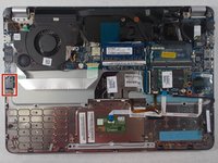
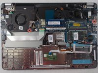
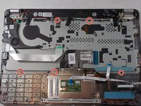
Flip the device over so that the back plate is facing upwards.
-
-
-
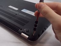
Using a small (size 0) Phillips head screwdriver, remove the twelve 5.5 mm external Phillips head screws that connect the back plate to the device.
-
-
-
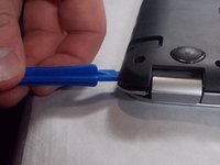
Using the plastic opening tool, gently pry off the back plate from the device.
-
-
-
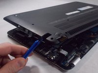
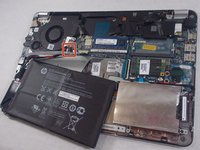
Move the ribbon cable so that it is no longer on top of the battery.
-
-
-
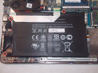
Using a small (size 0) Phillips head screwdriver, remove the three 3.5 mm Phillips head internal screws that hold the battery in place.
-
-
-
Lift up the battery and remove it from the slot as shown.
-
-
-
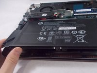
Use the plastic opening tool to disconnect the battery cable.
-
-
-
Lift up the battery and remove it from the device.
-
-
-
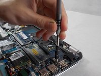
Using a size 0 Phillips head screwdriver, remove the four 3 mm size 0 screws attaching the hard drive casing to the device.
-
-
-
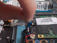
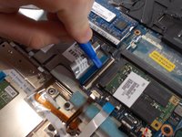
Unplug the hard drive from the hard drive plug.
-
-
-
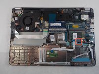
After removing the hard drive, you now must remove the motherboard. Start by pulling out the ribbon cable that attaches the touch pad to the motherboard.
-
-
-
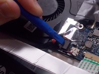
Using the plastic opening tool, pry out the small chip next to the touch pad that is attached via ribbon cable to the motherboard. Make sure to pry from the side that only has one small black bump, rather than the side that has two.
-
-
-
-
Using the plastic opening tool, flip up the clasp for the ribbon cable connecting the keyboard to the motherboard and then unplug the ribbon cable.
-
-
-
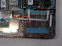
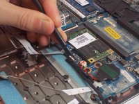
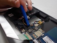
Using the plastic spudger, disconnect the hard drive plug from the motherboard.
-
-
-
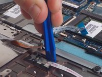
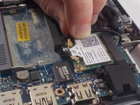
Now, remove the LAN adapter. Peel back the black plastic cover so that the LAN adapter is visible.
-
-
-
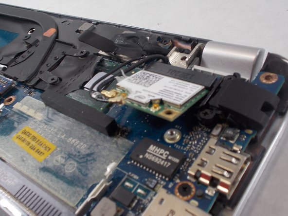
Pull off the two cables from the LAN adapter.
-
-
-
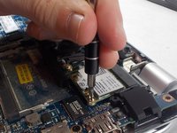
Using a size 0 Phillips head screwdriver, remove the two metallic 3 mm Phillips head screws.
-
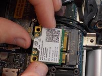
Once the screws are removed, the LAN adapter should pop up. Pull out the LAN adapter from its socket.
-
-
-
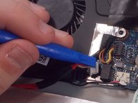
Use plastic spudger to remove black and red wire from the socket.
-
-
-
Using plastic spudger, disconnect power connector.
-
-
-
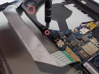
Disconnect display panel cable by pulling on black tab to unplug the cable from the socket
-
-
-
Using the plastic opening tool, flip up the clasp on the power button cable and unplug the power button cable from the socket.
-
-
-
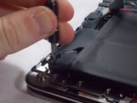
Remove clasp beneath the headphone port.
-
Using a size 0 Phillips head screwdriver, remove the 3 mm size 0 Phillips head screw that attaches the clasp to the device.
-
Then, take off the clasp.
-
-
-
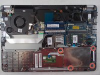
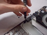
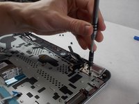
Using a size 0 Phillips head screwdriver, remove the two 3 mm size 0 screws attaching the motherboard to the device.
-
-
-
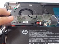
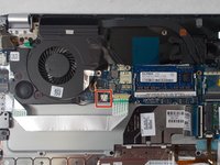
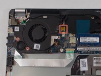
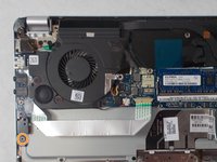
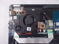
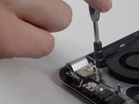
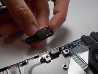
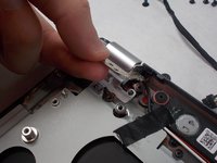
Remove the fan.
-
Use a size 0 Phillips head screwdriver to remove the 3 mm size 0 screw attaching the fan to the device.
-
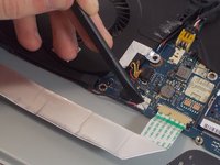
Pull the fan out of the slot and, using the plastic opening tool, unplug the connector cable from the socket.
-
-
-
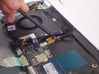
Unplug the cable attaching the keyboard to the motherboard.
-
-
-
Remove the subwoofer.
-
Using plastic opening tool, remove the red and black subwoofer cable.
-
Use a size 0 Phillips head screwdriver to remove the two 3 mm size 0 screws attaching the subwoofer to the device.
-
-
-
Use a size 0 Phillips head screwdriver to remove the 3 mm size 0 screw attaching the charging port clasp to the device.
-
Remove the charging port clasp.
-
-
-
Use a size 0 Phillips head screwdriver to remove the 3 mm size 0 screw attaching the black claspto the device.
-
Remove the black clasp.
-
-
-
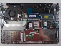
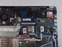
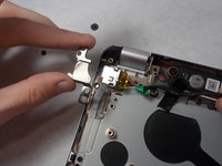
Lift up the motherboard and the power cable off of the device and place them to the side.
-
-
-
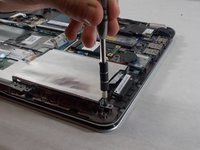
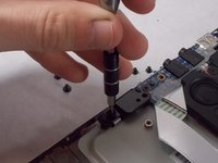
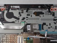
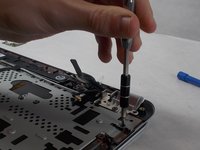
Use a size 0 Phillips head screwdriver to remove the four 3 mm size 0 screws securing the hinges to the device.
-
Lift up the hinges off of the keyboard.
-
-
-
Using a size 0 Phillips head screwdriver, remove all of the 3 mm size 0 screws attaching the keyboard to the device.
-
-
-
Lift up and remove the keyboard from the device.
-
-
-
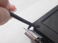
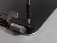
On the bottom corners of the screen are two plastic covers. Pry these off using the plastic spudger
-
Remove the two 3 mm size 0 Phillips screws on the left and right.
-
-
-
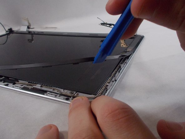
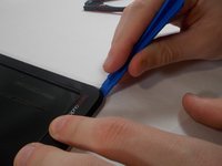
Pry open the plastic bezel around the screen using the plastic opening tool.
-
-
-
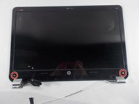
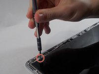
Remove the four 4.0 mm Phillips screws located at each corner of the screen using a Phillips #1 screwdriver.
-
-
-
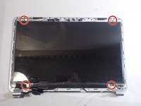
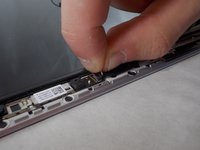
Remove the screen by pulling the metal tab at the top.
-
-
-
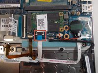
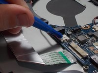
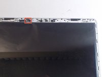
Disconnect the forty pin display connector located on thee backside of the bottom of the screen.
-


crwdns2935221:0crwdne2935221:0
crwdns2935229:02crwdne2935229:0
crwdns2915084:0crwdne2915084:0

UMass Dartmouth, Team S1-G3, Valliere Fall 2018 crwdns2935289:0UMass Dartmouth, Team S1-G3, Valliere Fall 2018crwdne2935289:0
UMASSD-VALLIERE-F18S1G3
crwdns2931471:05crwdne2931471:0
crwdns2935297:06crwdne2935297:0