crwdns2915892:0crwdne2915892:0
If your ElitePad is failing to turn on follow this troubleshooting guide before considering replacing the motherboard.
If your ElitePad’s touch screen is unresponsive follow this troubleshooting guide before considering replacing the motherboard.
crwdns2942213:0crwdne2942213:0
-
-
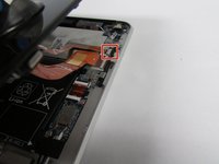
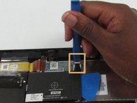
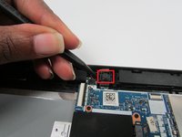
Using a Phillips #00 screwdriver, remove the two Phillips PM 1.4×3.2mm screws located next to the charging port.
-
-
-
Place the suction cup on the lower right corner of the tablet display glass, making sure to place the suction cup inside the edges of the border of the display glass.
-
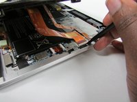
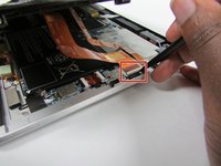
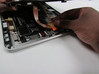
Insert a plastic pick in between the display and the tablet case. Then use a plastic removal tool to separate the display further.
-
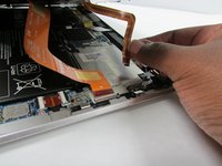
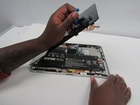
Pull on the suction cup while using the prying tool to separate the display from the tablet.
Might want to use the spudger tool to pry the screen up. We had difficulty using the pry tool. to pull up the screen.
display is held to the base by 3 magnetized tips on the right edge and 4 on the bottom edge (charging port) of the display. the ones on the right are at the center and at each corner before the display curves. on the bottom edge, 2 are at the corners and the other 2 are 1.5” inward. the top and left edges are friction tips. prying along the edges releases the magnetic tips from the base.
-
-
-
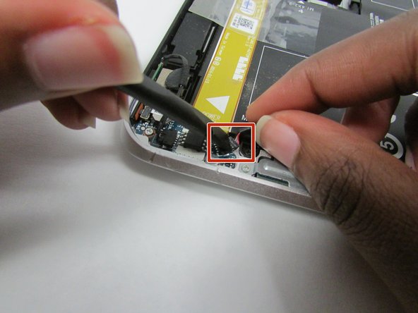
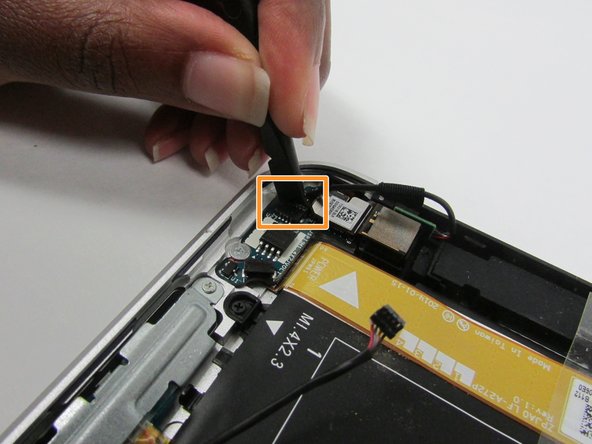
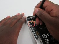
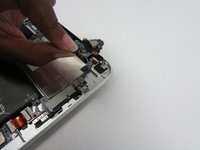
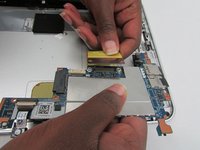
Release the zero insertion force (ZIF) connector to which the TouchScreen cable is attached, and then disconnect the TouchScreen cable from the system board.
Need to Add the spudger tool and differentiate between the black spudger tool and the blue plastic pry tool.
When disconnecting the cables we found that the wording “ push the tab” was confusing. We had to pull up the black tab for the ribbon cables to disconnect.
i didn’t know what a spudger tool was but didn’t find any black tab to push or pull. both of my cables were taped on the bottom and top. they also had adhesive on the bottoms. i removed the tape, gently lifted the cables away from the silver cover the were stuck to and pulled the cables out from their zif sockets.
i figured out how the zif sockets work and am correcting my previous comment. on my unit, the zif sockets are black and the release levers are white. i “opened” the zif sockets by flipping up the white edges that were furthest from the cables. i removed the tape, gently lifted the cables away from the silver cover they were stuck to and pulled the cables out of the zif sockets.
-
-
-
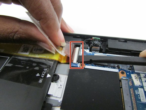
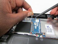
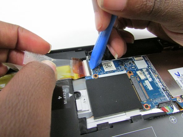
Release the ZIF connector to which the display cable is attached, and then disconnect the display cable from the system board.
-
-
-
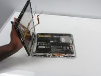
Remove the display from the tablet.
The second shot here is blurry. Do you have a clearer version?
-
-
-
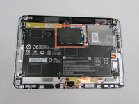
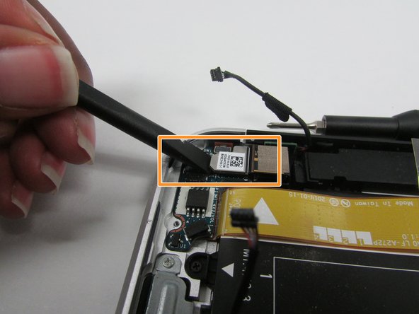
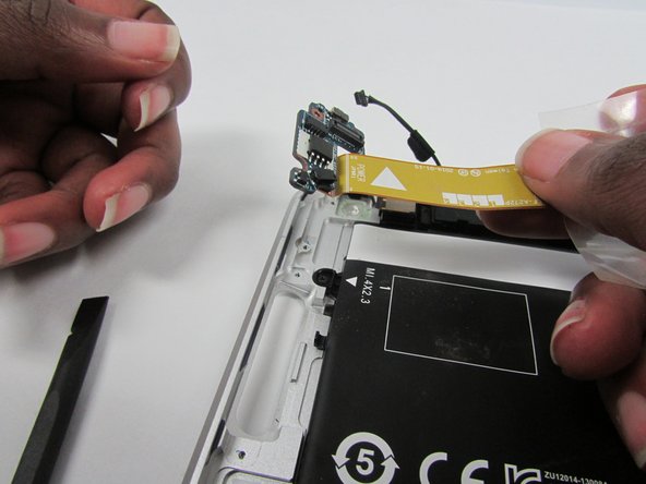
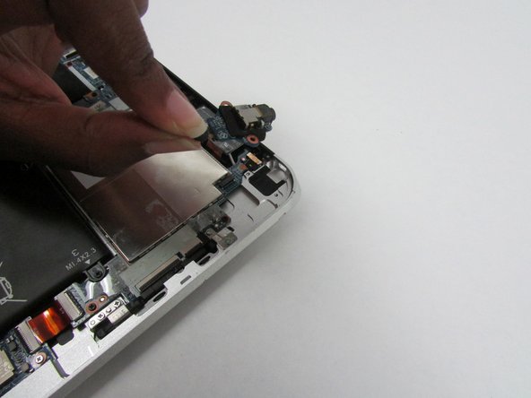
Locate the NFC antenna.
-
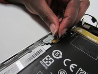
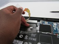
Release the ZIF connector to which the NFC antenna cable is attached.
The first shot here is blurry and kind of weirdly composed. Can you change it?
on my unit, the NFC antenna zif socket is black and the release lever is white.
-
-
-
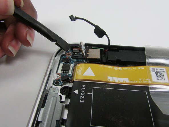
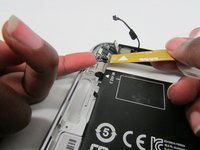
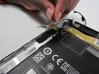
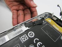
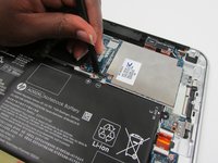
Detach the NFC antenna from the surface of the system board.
-
Remove the NFC antenna.
This shot is a bit blurry as well—consider also pulling back a bit.
my antenna had thin black foam and was sitting on top of the single sided tape connected to the power button board ribbon cable.
-
-
-
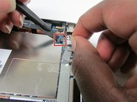
Locate the power button board and attached ribbon cable.
-
Locate the volume button board.
-
-
-
-
Disconnect the volume button board cable from the power button board.
-
Disconnect the left microphone cable from the power button board.
-
-
-
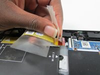
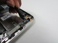
Lift the clear tape which is attached to the power button board cable and the motherboard.
-
Release the ZIF connector to which the power button board cable is attached.
-
Detach the power button board cable from the surface of the battery by pulling away from the connector.
-
-
-
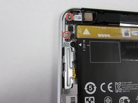
Remove the Phillips PM1.3×2.0mm broad head screw and the Phillips PM1.3×2.0mm screw that secure the power button board to the bottom cover.
-
Gently push upwards on the tab
The red step should be broken in to two steps. For better understanding.
We’re pretty sure this step includes an incorrect picture for this step. Also “Use Spudger…” should be included as it’s shown in photos.
-
-
-
Remove the power button board and cable.
-
-
-
Remove the two Phillips PM1.5×2.0mm screws that secure the volume button board to the bottom cover.
-
-
-
Remove the volume button board and cable.
-
-
-
Locate the audio jack board.
-
-
-
Disconnect audio jack board cable from the motherboard.
-
Remove the two Phillips PM 1.3x2.0mm screws that secure the audio jack board from the housing.
-
Remove the audio jack board.
-
-
-
Locate the power button board ribbon cable.
-
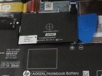
Locate the battery to motherboard connector.
-
-
-
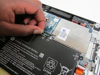
Lift the clear tape attached to the power button board ribbon cable.
-
Disconnect the ZIF connector by using a plastic removal tool to gently pull up on the black tab.
-
Lift the power button board ribbon cable up and away so that it doesn't get in the way of the battery during removal.
this zif connector was the same color as the pic. gently lift the power button board ribbon cable which had adhesive underneath and the clear tape on top. my unit had a copper rectangle on top of the battery to the top power button assembly which i gently peeled away from the battery. i re-routed a cable that was attached to the guides on the left edge of the battery.
-
-
-
Disconnect the battery to system board connector by pushing gently on it with a plastic pry tool and then pull it away from the system board.
Missing battery remover step.
the connector is too long to pull out at this point. remove the connector while lifting out the battery in step 12.
-
-
-
Using a philips 00 screw driver take out the six Phillips PM1.3×2.0mm screws
-
-
-
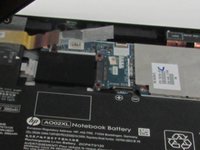
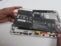
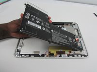
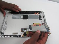
Carefully lift the battery away from the bottom cover.
-
-
-
Release the webcam from the housing.
-
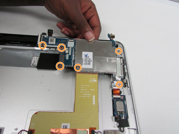
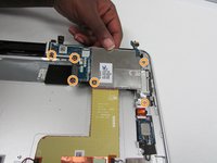
Remove the six Phillips PM 1.3 x 2.0mm screws that secure the board to the bottom cover.
There are six screws not five. The sixth is to ‘above’ the lone screw on the right.
-
-
-
With the backside of the motherboard exposed remove the two Phillips 1.3 mm screws.
-
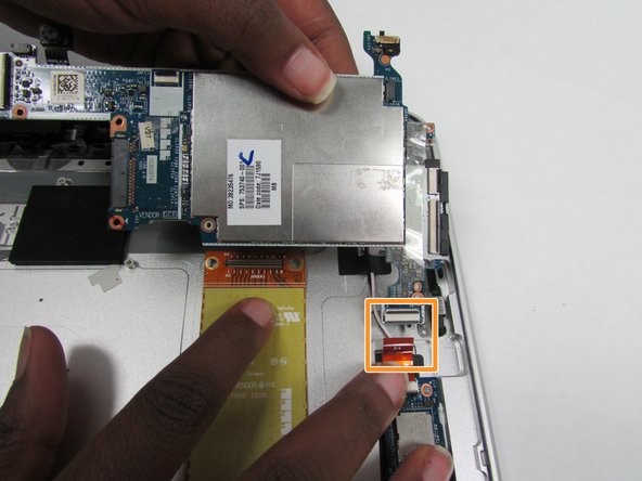
Disconnect the ribbon connector on the back of the board.
-
Remove ribbon connector that connects to the WLAN module.
-
Remove the motherboard.
-


To reassemble your device, follow these instructions in reverse order.
To reassemble your device, follow these instructions in reverse order.
crwdns2915084:0crwdne2915084:0

Embry-Riddle Aeronautical University, Team S3-G2, Watkins Summer 2019 crwdns2935289:0Embry-Riddle Aeronautical University, Team S3-G2, Watkins Summer 2019crwdne2935289:0
ERAU-WATKINS-SU19S3G2
crwdns2931471:04crwdne2931471:0
crwdns2935297:06crwdne2935297:0
crwdns2947410:01crwdne2947410:0
I am looking for the hard drive in the tablet I want upgrade the capacity of the
have a safe place to save the 8 tiny screws. the screwdriver will need a thin shaft to get inside the holes.
Teddy Sam - crwdns2934203:0crwdne2934203:0