crwdns2915892:0crwdne2915892:0
Use this guide to replace the Motherboard on the HP Elitebook 1040 G4. The Motherboard is the backbone that ties all components of the computer together. It moves power throughout the device and provides a central place for communication. If you are noticing problems with your computers speed, graphics, or hardware, you may need to replace your motherboard.
To complete this guide, you will need a #T5 Torx head screwdriver and a Phillips #0 and #00 screwdriver.
Before beginning, be sure to completely power off your computer.
crwdns2942213:0crwdne2942213:0
-
-
Use a T5 Torx screwdriver to remove the eight 5 mm screws securing the back cover to the chassis.
-
-
-
Lift the back cover up and off the device.
-
-
-
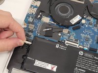
Use a Phillips #00 screwdriver to remove the eight 4 mm screws securing the battery to the motherboard.
-
-
-
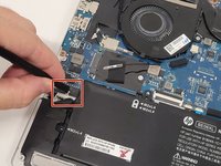
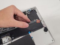
Use a plastic spudger to carefully disconnect the battery pin connector from its port, slowly lifting the pin connector from each side until it releases.
-
-
-
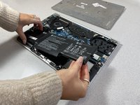
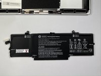
Lift and remove the battery from the device.
-
-
-
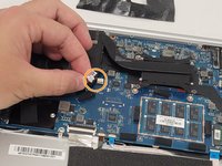
Using the Phillips #00 screwdriver, remove the single 5 mm screw securing the SSD to the motherboard.
-
-
-
Lift the SSD up and out of the device.
-
-
-
-
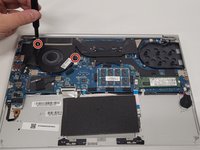
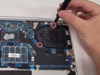
Using the Phillips #0 screwdriver, remove the two silver 5 mm screws surrounding the fan.
-
-
-
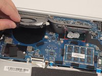
Remove the electrical tape to expose the heat sink screws.
-
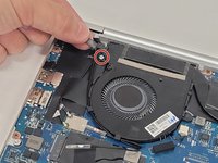
Using the Phillips #0 screwdriver, unscrew the four screws securing the heatsink to the motherboard.
-
Carefully disconnect the pin connector by pulling it from its slot.
-
-
-
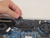
Carefully remove the wires from the clip to the left of the fan.
-
-
-
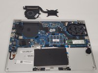
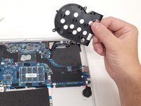
Lift and remove the fan and heatsink assembly from the device.
-
-
-
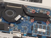
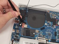
Using the Phillips #0 screwdriver, remove the five black 4 mm screws securing the motherboard to the device.
-
-
-
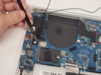
Using the same Phillips #0 screwdriver, remove the two silver 6.5 mm screws from the secondary fan placeholder.
-
Remove the fan placeholder from the device.
-
-
-
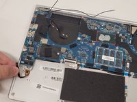
Carefully disonnect the "Main" and "Aux" cables from the dual band wireless driver.
-
-
-
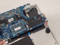
Remove the ZIF connector from the bottom left of the motherboard by lifting the small grey tab, then pulling the connector out of the slot.
-
For more information on properly disconnecting and removing Zero Insertion Force (ZIF) connectors, please visit this guide.
-
-
-
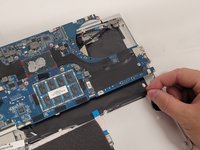
Disconnect and remove the four ZIF connectors from the bottom middle of the motherboard by lifting the small locking tabs, then pulling the connectors out of their slots.
-
-
-
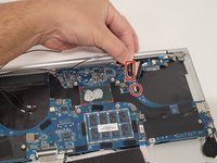
Remove the pin connector from the top right corner of the motherboard.
-
-
-
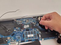
Remove the ZIF connector from the top right corner of the motherboard by lifting the locking tab, then pulling the connector out of the slot.
-
-
-
Remove the pin connectors in the top right corner of the motherboard by lifting them straight up. The longer, top, connector has a pull tab connected to it to assist in pulling it out.
-
-
-
Remove the RTC battery pin connector from the underside of the motheroard.
-
-
-
Carefully lift and remove the motherboard.
-


To reassemble your device, follow these instructions in reverse order.
crwdns2935287:0crwdne2935287:0

Clemson, Team 4-1, Hunter Fall 2021 crwdns2935289:0Clemson, Team 4-1, Hunter Fall 2021crwdne2935289:0
CLEM-HUNTER-F21S4G1
crwdns2931471:05crwdne2931471:0
crwdns2935297:010crwdne2935297:0