crwdns2915892:0crwdne2915892:0
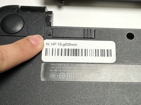
This is a guide on how to replace the RAM on your HP 15-g029wm. This guide may be needed if you're encountering problems with your HP 15-g029wm's screen freezing. There is only one step in this guide that describes how to remove the RAM from your motherboard to replace it.
crwdns2942213:0crwdne2942213:0
-
-
Unplug any charging cord or accessories connected to the device before beginning.
-
-
-
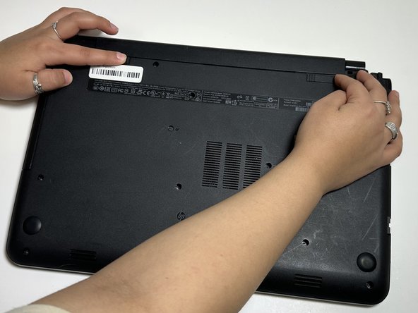
Place the laptop bottom-side up on a secure, flat surface.
-
-
-
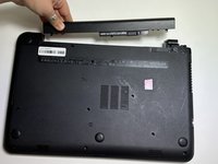
Slide each of the two switches that secure the battery to the left.
-
-
-
Use your hands to gently pull the disconnected battery out of the device.
-
-
-
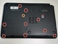
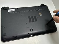
Remove the following Phillips screws on the lower case:
-
Nine 5 mm
-
One 6 mm
-
-
-
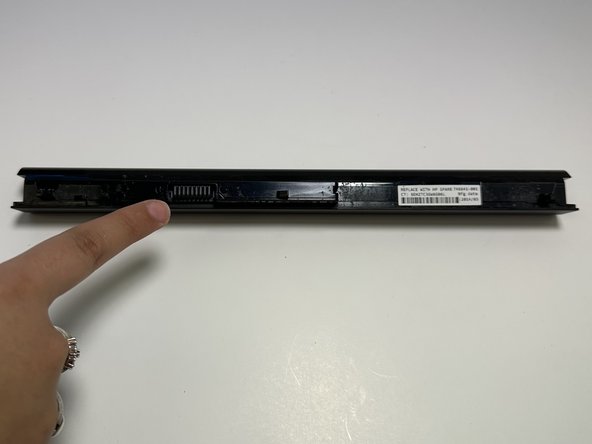
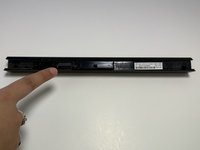
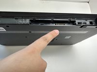
Slide the optical drive directly out of its slot.
-
-
-
Remove the two 2 mm Phillips screws on the lip of the optical drive slot.
-
-
-
-
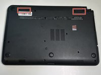
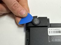
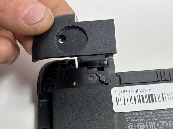
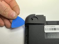
Use an opening pick to remove the two circular rubber feet near the laptop hinges.
-
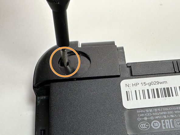
Remove both of the 8 mm Phillips screws.
-
-
-
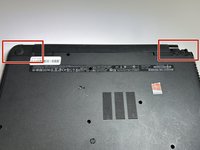
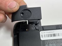
Use an opening pick to pry up and remove the left hinge cover.
-
Use an opening pick to pry up and remove the right hinge cover.
-
-
-
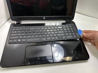
Flip the device face up and open the lid.
-
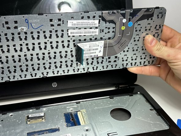
Insert an opening pick under the keyboard and pry around the perimeter of the keyboard until it fully releases.
-
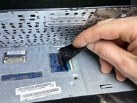
Lift the keyboard slightly.
-
Use your fingers or an opening pick to unlock the ZIF locking flap that secures the keyboard ribbon cable.
-
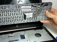
Disconnect the keyboard ribbon cable.
-
Lift the keyboard off.
-
-
-
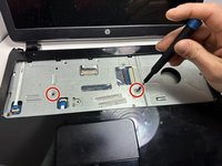
Remove two 5 mm screws using a Phillips screwdriver.
-
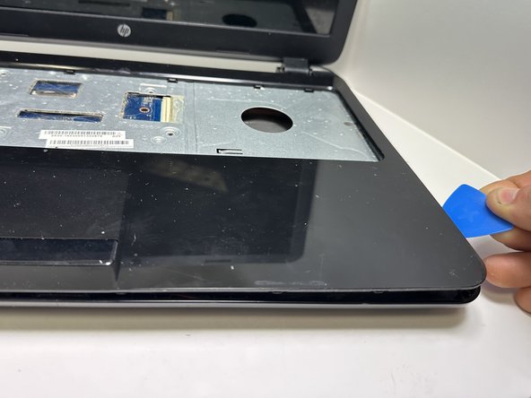
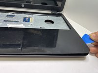
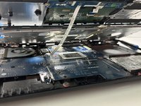
Insert an opening pick in the seam between the top case and chassis.
-
Slide the opening pick around the edge of the device to separate the top case from the chassis.
-
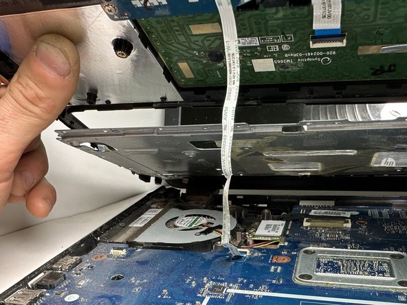
Slightly lift the top case up and away from the chassis.
-
-
-
Use your fingers or an opening pick to flip up the black ZIF locking flap.
-
Disconnect the ribbon cable.
-
Lift off the top case.
-
-
-
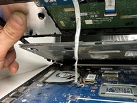
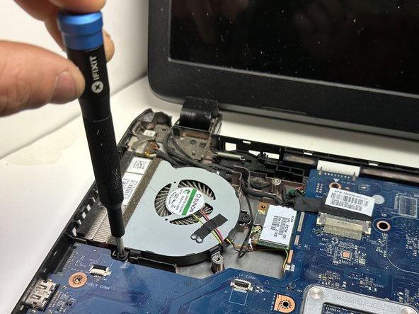
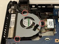
Use a Phillips screwdriver to remove the three 5 mm screws that secure the fan.
-
-
-
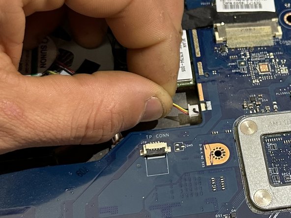
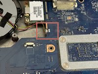
Gently "walk" the fan connector directly out of its motherboard socket.
-
-
-
Lift the fan up and out of the chassis.
-
-
-
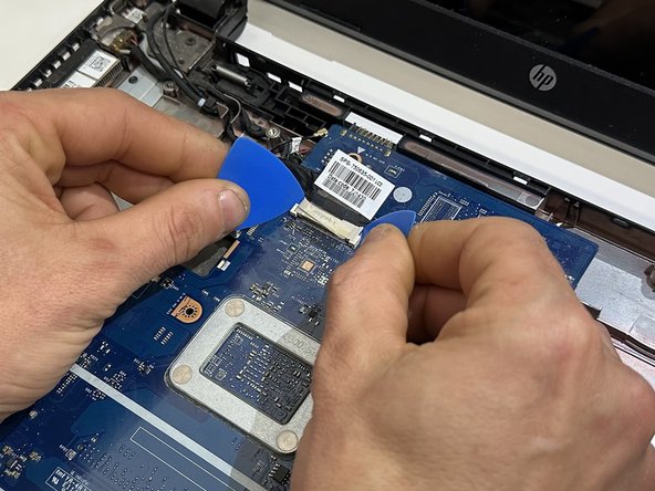
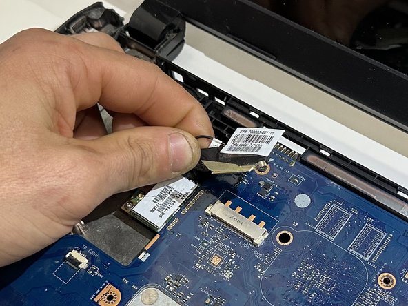
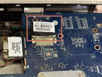
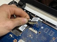
Use two opening picks to disconnect the display cable.
-
-
-
Use an opening pick to gently "walk" the white speaker connector directly out of its port.
-
-
-
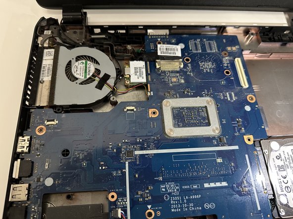
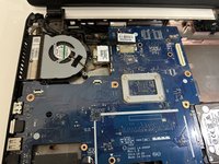
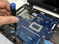
Remove the four 3 mm screws that secure the motherboard.
-
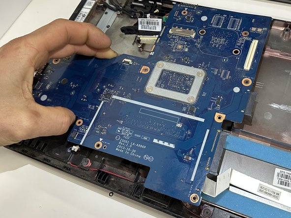
Lift the front edge of the motherboard slightly.
-
-
-
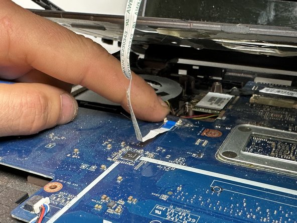
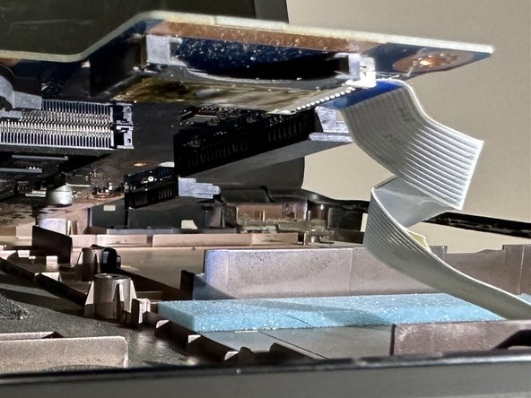
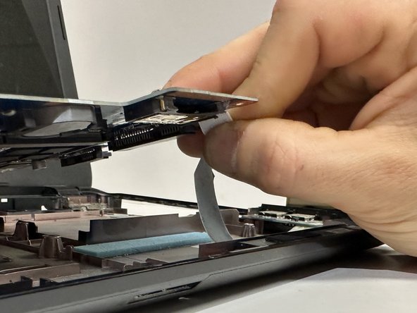
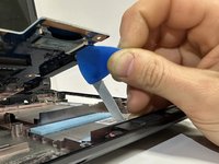
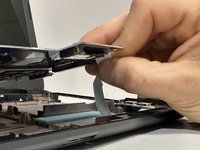
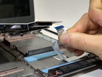
Use an opening pick or your fingers to release the ZIF locking flap.
-
Pull the ribbon cable out of its port.
-
-
-
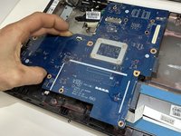
The motherboard is now fully disconnected and able to be removed from the chassis by lifting it out with your hands.
-
Remove the following components for your new motherboard: Heatsink, RAM, CMOS battery.
-
-
-
Two clips secure the RAM module in place, one on each side. Using your fingers, spread the clips away from the RAM module
-
Slide the RAM module straight out of its socket.
-


To reassemble your device, follow these instructions in reverse order.
To reassemble your device, follow these instructions in reverse order.
crwdns2935221:0crwdne2935221:0
crwdns2935227:0crwdne2935227:0

crwdns2915084:0crwdne2915084:0

Austin Community College, Team 18-2, Watkins Spring 2024 crwdns2935289:0Austin Community College, Team 18-2, Watkins Spring 2024crwdne2935289:0
AUSTINCC-WATKINS-S24S18G2
crwdns2931471:04crwdne2931471:0
crwdns2935297:06crwdne2935297:0