crwdns2915892:0crwdne2915892:0
If the keys on the keyboard are not working or the touchpad is not responding, they may need to be replaced. To replace one of the systems, the entire keyboard/touchpad surface needs to be replaced.
crwdns2942213:0crwdne2942213:0
-
-
Turn the device and lay it upside-down on a flat surface so the base of the computer is facing upwards.
-
-
-
Identify the two (2) sliding lock mechanisms on either side of the battery and slide them towards the center.
-
-
-
Pull the battery slightly up and out to remove.
-
-
-
Remove the rubber feet on the bottom of the device to access all the screws.
-
-
-
Unscrew the twelve 9 mm JIS #0 screws on the back of the device.
-
Gently remove the optical drive (CD reader) to more easily separate the base.
-
-
-
Unclip the keyboard surface from the base using an iFixit opening tool around the entire border.
-
-
-
Separate the base of the computer from the component assembly.
-
-
-
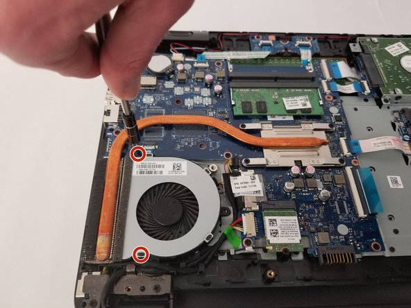
Remove the two 6.5 mm JIS #0 screws holding the cooling fan to the base.
-
-
-
Unplug the fan cable from the motherboard.
-
-
-
Remove the three 3 mm JIS #0 screws from the hard drive.
-
-
-
-
Unplug the hard drive from the motherboard.
-
-
-
Unplug display from the motherboard.
-
-
-
Unplug the power port from the motherboard.
-
-
-
Unplug the display wire from the wireless adapter.
-
-
-
Remove the single screw from the wireless card and gently remove the drive.
-
-
-
Unplug the keyboard from the motherboard.
-
-
-
Unplug the optical drive connection from the motherboard.
-
-
-
Remove the memory chip from the motherboard by pushing the clips away from the chip.
-
-
-
Unplug both (2) wires for the touch-pad from the motherboard.
-
-
-
Unplug the speakers from the motherboard.
-
-
-
Unplug the power button from the motherboard.
-
-
-
Unscrew the four 3mm JIS #0 screws that secure the motherboard.
-
-
-
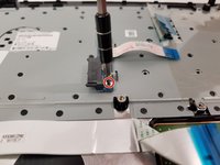
Remove the two 3mm JIS #0 screws that secure the touchpad board.
-
-
-
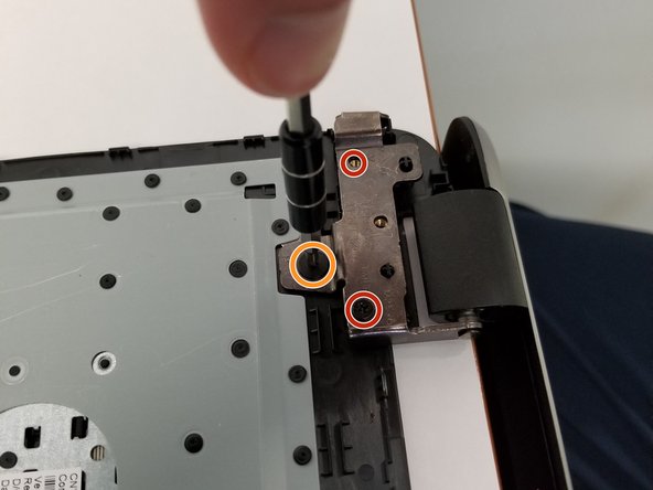
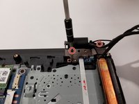
Remove the display by unscrewing the four 3mm JIS #0 screws.
-
Remove one 2mm JIS #0 screw.
-
-
-
Lift the power port from its cradle.
-
-
-
Unscrew the one 3mm JIS #0 screw holding the power button board to the device.
-
-
-
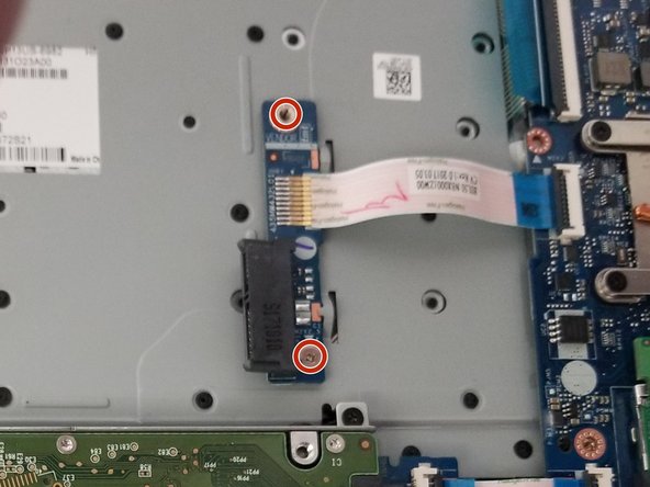
Unscrew the two 3mm JIS #0 screws that hold the optical drive (CD-reader) connection to the device.
-
-
-
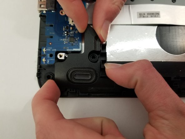
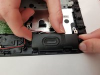
Remove the two (2) speakers located on the botten edge of the keyboard cover.
-
-
-
Make sure there is nothing else attached to the keyboard cover so all that remains is the keyboard and touch-pad.
-


To reassemble your device, follow these instructions in reverse order.
crwdns2935221:0crwdne2935221:0
crwdns2935229:02crwdne2935229:0

crwdns2935287:0crwdne2935287:0

Oregon Institute of Technology, Team S1-G5, Lancaster Winter 2019 crwdns2935289:0Oregon Institute of Technology, Team S1-G5, Lancaster Winter 2019crwdne2935289:0
OIT-LANCASTER-W19S1G5
crwdns2931471:04crwdne2931471:0
crwdns2935297:08crwdne2935297:0